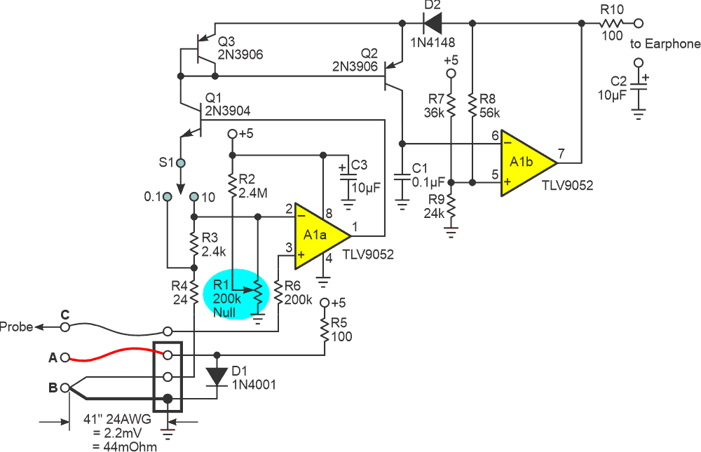
Recently, frequent and favorite contributor Nick Cornford gave us a cool and novel acoustic-interface design for a super sub-ohmmeter capable of audibly sniffing out defects in PWBs: “Tuneful track-tracing” (Ref. 1).
Figure 1’s design shamelessly nicks Cornford’s concept. It stretches the resistance sensing range by a few decades, thus spanning single-digit milliohms to double-digit ohms. This adds extra versatility for locating spurious connections in both loaded boards and boards with shorts in ground planes. Here’s how it works.
 |
|
| Figure 1. | Audible milli-ohmeter output frequency is linear versus resistance over several orders of magnitude. |
A 50-mA excitation current is provided to the PWB under test by R5 via connections A (source) and B (half-Kelvin sense and current return). D1 limits the maximum developed voltage to ~700 mV. This prevents (potentially damaging) forward bias of components on loaded boards in case the short being sniffed unexpectedly disappears.
The current return side of B consists of the (approximately) known resistance (44 mΩ) of a 41-inch length of 24 AWG copper wire. The resulting 44 mΩ × 0.05 A = ~2 mV drop provides a null reference for the A1a voltage to current amplifier. We’ll discuss that more shortly (no pun?).
The probe voltage mode signal is converted to current mode by transconductance amplifier Q1/A1a, the associated resistor network, and range selection switch S1. R6 provides static-discharge protection for A1’s input pin while developing only µV of offset from A1’s pA-level bias current. S1 provides two frequency/resistance ranges: 100 Hz/Ω and 10 kHz/Ω.
The shorts-sniffing process consists of sliding probe C along the problematic path on the PWB while listening to the resulting audio output. Its frequency rises or falls with the resistance between the probe contact and the Kelvin connection B rises or falls. Maximum resolution results if a quick initial nulling of offset voltage is done via Null pot R1 adjustment. It provides up to ±2 mV of input offset adjustment to cancel the op-amp offset for a zero (or near) Hz output when probe C is held at the point of excitation current entry to the PWB under test. Of course, you won’t hear the actual fundamental frequency when oscillation is that slow, but only the (annoying) buzz of the square wave rising and falling edges.
The A1b (more or less symmetrical) triwave/squarewave oscillator itself is built around the 2way current mirror comprising Q2, Q3, and D2 as described in this earlier DI: “A two-way mirror—current mirror that is” (Ref. 2).
The mirror sources current into timing cap C1, linearly ramping it up, when A1b’s pin 7 is positive, and sinks current when pin 7 is low, ramping it down. The resulting 1 Vpp triwave on C1 and the squarewave on pin 7 are approximately symmetrical.
Its actual frequency can be over the range from the subsonic to the ultrasonic, but of course (by definition), little information will be relayed to your ear by either. Thence cometh the utility of range switch S1.
References
- Cornford, Nick. "Tuneful track-tracing."
- Woodward, Stephen. "A two-way mirror—current mirror that is."