This project presents the design and implementation of a dual-fan PWM cooling circuit, integrating a compact and efficient power supply with intelligent fan speed regulation. The circuit consists of two main parts: a 6 W isolated flyback converter that converts universal 85 V–260 V AC to a stable 12 V DC output, and a microcontroller-based control unit utilizing an ATtiny13 MCU.
The control unit reads temperature data from a 10K NTC thermistor and dynamically adjusts the FAN speed via PWM, ensuring optimal cooling performance while minimizing noise and power consumption. The circuit is designed to drive one or two 12 V FANs, automatically regulating their speed in response to temperature variations. Special attention has been given to the PCB layout to comply with EMC/EMI standards, enhancing reliability and reducing electromagnetic interference. This design suits applications requiring efficient and autonomous thermal management in electronic enclosures, power supplies, and other heat-sensitive environments.
Circuit analysis
Figure 1 shows the schematic diagram of the device. The schematic has two parts: the first part is an AC to DC flyback converter and the second part is the FAN controller.
 |
|
| Figure 1. | Schematic diagram of the temperature-controlled dual-fan cooling device. |
“AC” is the input terminal for the AC voltage, in the range of 85 V to 260 V. F is a 15R-1W 0309 MELF fuse resistor. Using such a component instead of an ordinary fuse has several advantages: limiting the inrush current, acting as a fuse, and reducing the noise by creating an RC filter with C3. BR is a bridge rectifier for AC to DC conversion and C3 is the HV line (net: DCLine) capacitor that reduces voltage ripple. Try to use a high-quality capacitor for this function otherwise a low-quality one/low ripple-current will dry out too soon and might damage the controller.
R3, D3, and C4 build an RCD snubber circuit. Such a snubber dampens the high voltage spikes/ringing on the transformer primary (Drain of the MOSFET) and protects the MOSFET. This is the main purpose of using a snubber although it potentially reduces the EMI if designed and tested correctly. In this circuit, the MOSFET is embedded in the controller.
IC2 is the DK106 controller chip. The controller switching frequency is 65 kHz and operates with only a few passive components. It does not need a startup resistor and an auxiliary winding.
C10 reduces high-frequency noises on the feedback pin. C9 is a bypass capacitor for the VCC pin. OP is the PC817 optocoupler providing a galvanically isolated path for the controller to sense any variation in the output voltage and reflect it to the controller. D1 is the output Schottky diode to rectify the secondary and C5 reduces the output noise. When D4 lights up, it indicates the output voltage is at its correct level.
R2 and C7 build a strong lowpass RC filter to minimize the noise as much as possible because the microcontroller uses its internal ADC to read the NTC (temperature) voltage and an ADC unit is sensitive to noise. REG is a SOT-89 78L05 regulator to stabilize the voltage and provide a regulated +5 V rail for the microcontroller (IC1). C8 and C6 stabilize the regulator. C6 is a tantalum-type capacitor that acts better than ceramic ones at the LDO output.
IC1 is an ATtiny13 microcontroller and ISP is a 5-pin 2.54 mm male pin header for AVR ISP programming. C1 and C2 are decoupling capacitors for the supply rail of the IC1. Q1 is the Si2310 SOT-23 N-Channel MOSFET to drive the FANs and D2 protects the Q1 against reverse spikes. D2 must be a Schottky type similar to SS36 because the PWM frequency is 25 kHz and an ordinary diode such as an M7 would not act quickly enough. NTC is an XH-2P connector for the 10K NTC. When the temperature increases, the resistance of the NTC and ADC voltage decreases and vice versa.
Transformer
Figure 2 shows the winding information. The ferrite core is EE19-8-5 and bobbin is 3+3 vertical.
 |
|
| Figure 2. | Winding pattern of the transformer. |
To wind the transformer, follow this procedure: Start by winding the primary clockwise or counterclockwise. Then install the ferrite cores in place (in the bobbin) and measure the inductance of the primary winding using an LCR meter. If you can select the measurement frequency on your LCR meter, the best frequency is 65 kHz (switching frequency of the transformer), otherwise, set it to 40 kHz or 100 kHz. Grind the middle leg of the ferrite core and measure the inductance till you reach a value close to 3.1 mH. A small tolerance is acceptable and does not cause a problem. Wrap 2–3 turns of transformer tape around the primary, then wind the secondary according to the instructions.
The primary leakage inductance can be measured by connecting an LCR meter to the primary and short-circuit all other windings.
PCB layout
Figure 3 shows the PCB layout. It’s a two-layer PCB, with a mixture of SMD and through-hole components.
|
|||||
| Figure 3. | PCB layout of the temperature-controlled dual-fan cooling circuit. | ||||
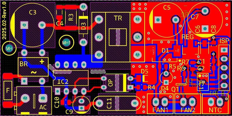
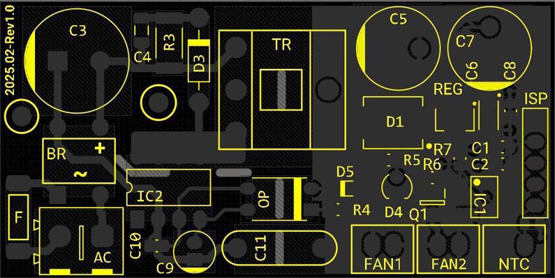
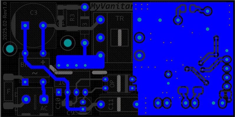
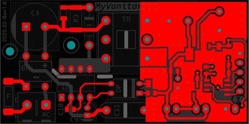
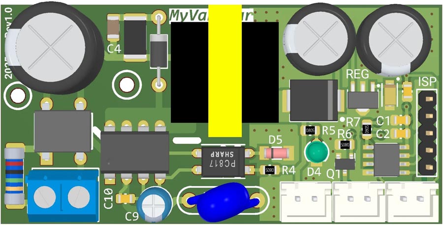
I have followed these routing techniques: The trace from the drain pin to the transformer is as short as possible. The bypass capacitor (C9) is close to the VCC pin. The snubber (clamp) circuit is as close as possible to the transformer. Traces to the Y capacitor are as short as possible. The loop area of the secondary (Schottky diode and the adjacent capacitor to the ground) is small. Figure 4 shows the PCB board assembly drawing.
 |
|
| Figure 4. | Assembly drawing of the PCB board. |
Code
You can download the Code/Gerber files from the Downloads section. The PWM is configured through AVR registers and the frequency is 25 kHz.
Assembly and test
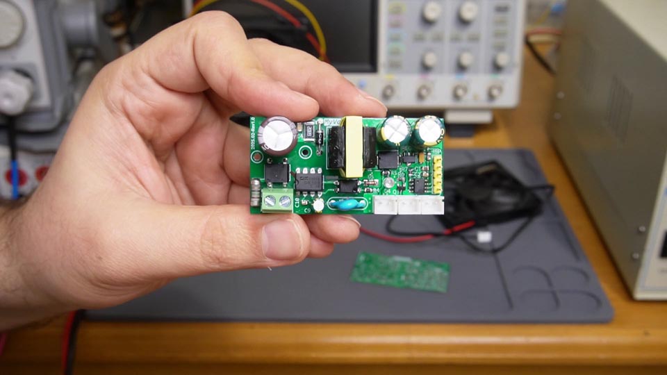
Figure 5 shows the assembled PCB. Testing the device is easy. Connect a 10K NTC to its connector and warm up the sensor (for example using a hot air gun or a hair dryer). You can modify the thresholds and FAN speed in the code based on your needs.
 |
|
| Figure 5. | Assembled PCB. |
Materials on the topic
- Datasheet Atmel ATtiny13
- Datasheet Dongke Semiconductor DK106
- Datasheet Texas Instruments LM78L05
- Datasheet First Silicon PC817
- Datasheet UMW Si2310
- Datasheet UTC DB107G
- Datasheet Vishay SS36
- Datasheet Taiwan Semiconductor SS310