This project is a simple, low-voltage push-pull PWM controller using the TI LM5032 chip and two MOSFETs. It's suitable for applications like DC-DC converters or Tesla coil drivers. Frequency, current sensing, and soft start are configured via external components.
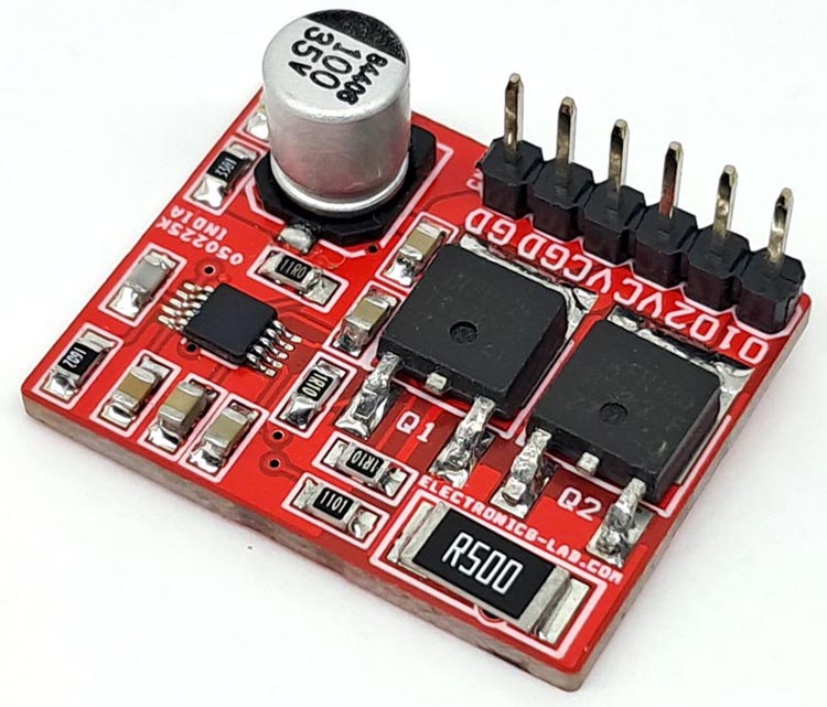
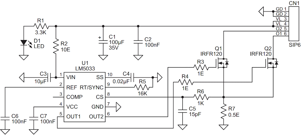
This is a simple low voltage push-pull voltage mode PWM controller based on LM5032 chip from TI (Figure 1). The board is build around LM5032 chip and two 100 V 7 A MOSFETs. It can be used in simple DC-DC converter, Tesla coil driver etc. The frequency can be changed with resistor R5. Resistor R7 play roll of current sense. Capacitor C4 configures the soft start function. Output is square wave open drain.
 |
|
| Figure 1. | Schematic diagram of a PWM controller. |
Frequency selection
- R5 16K = frequency 339 kHz
- R5 8.2K = frequency 600 kHz
- R5 26.7K = frequency 200 kHz
Features
- Power supply 15 V to 30 V DC
- Maximum load 1 A (MOSFET 7 A)
- Operating frequency 339 kHz
- Thermal shutdown
- Over current protection 1 A
- PCB dimensions 27.31 × 21.75 mm
The LM5033 high-voltage PWM controller contains all the features necessary to implement push-pull, half-bridge, and full-bridge topologies. Applications include closed-loop voltage mode converters with a highly regulated output voltage, or open-loop DC transformers such as an Intermediate bus converter (IBC) with an efficiency greater than 95%. Two alternating gate driver outputs with a specified deadtime are provided.
The LM5033 includes a start-up regulator that operates over a wide input range from 15 V to 100 V. Additional features include: precision voltage reference output, current limit detection, remote shutdown, soft start, sync capability, and thermal shutdown. This high-speed IC has total propagation delays less than 100 ns and a 1-MHz capable oscillator.
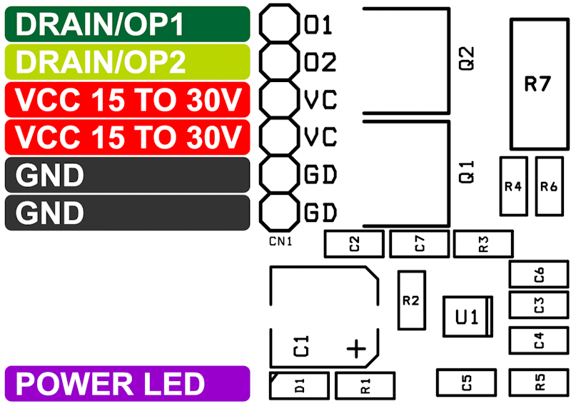
Figure 2 shows the controller connection diagram.
 |
|
| Figure 2. | The PWM controller connection diagram. |
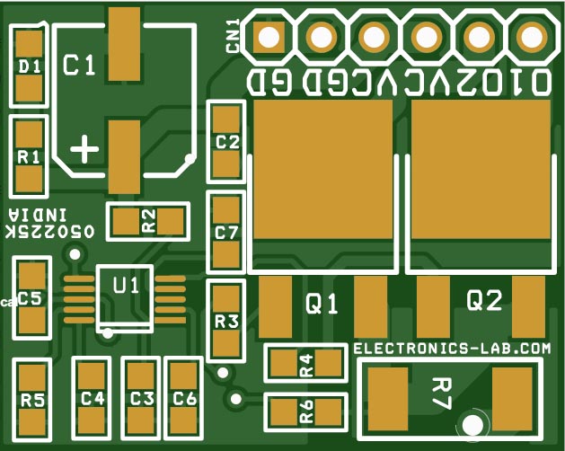
The Gerber project files can be downloaded from the link in the Downloads section. The PCB layout is shown in Figure 3. Table 1 shows the bill of materials.
| Table 1. | List of circuit components | ||||||||||||||||||||||||||||||||||||||||||||||||
|
|||||||||||||||||||||||||||||||||||||||||||||||||
 |
|
| Figure 3. | The PCB layout. |