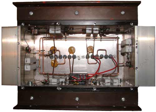
The enclosure above contains a wind generator dump load. It was designed to be mounted at a remote repeater site where the source of power is a wind generator.
When the battery is fully charged the voltage on the terminals will reach 14.1V. At this point the voltage should not be allowed to increase. By using a dump load any excess power that the wind generator produces is wasted as heat rather than charge a battery. In wind generator systems at home this waste power could be used for something useful such as heating a hot water cylinder, but at the top of a hill the best thing is to disapate it into the air.
Circuit Diagram
The basic circuit diagram is very simple. Q1 is an emitter follower which gives a low impedance output when the input voltage rises too high. Q2 is a gain stage that gives the dump load a sharp turn on knee. Q3 is a power device that then drives the MOSFETs. In my setup a 13V zenner and a 1N4001 produced a maximum voltage on the input of 13.9V.
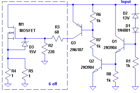
The circuit will draw as much current as it needs to reduce the voltage at the input to 13.9V. It works with the internal resistance of the wind generator windings to drop the voltage. My setup uses 6 STP80NF12 MOSFETs to draw the current. I'm hoping that this would be able to handle 20-25Amps. You can scale the number of MOSFETs depending on the MOSFET current rating and your needs.
Construction
The MOSFETs are mounted directly to the case, without the use of any insulating material. This is done to get the best thermal contact with the heatsink. The down side of this is that the case to connected directly to the battery and wind generator positive terminals. The majority of the power is dissipated in the MOSFETs, the resistors in the source are only there for current balancing.
Four heatsinks were bolted together at their corners to produce the sides of a box. Aluminum plate was used on the top and bottom to finish the box off. Between all the joints silicon sealant was used to stop water penetrating. Two buses were made out of 1.5mm copper wire to connect all the MOSFET drains and the ground points on the resistors. The control circuit, which can be seen at the top left of the enclosure, has been made on small piece of PCB, using a scalpel to make PCB islands.
The small circuit seen at the bottom is used to turn on addition loads when the battery is full. It monitors the voltage on the output of Q3 to find out when the dump load is dissipating energy. When the voltage is high enough it turns a relay on.
I have include additional protection on the inputs. I have one 90V surge arrestor and 30V varistors. These should allow the unit to survive any impulses that are induced onto the cabling. There are 15V zenners across each MOSFET to stop the gate-source voltage getting to dangerous levels.