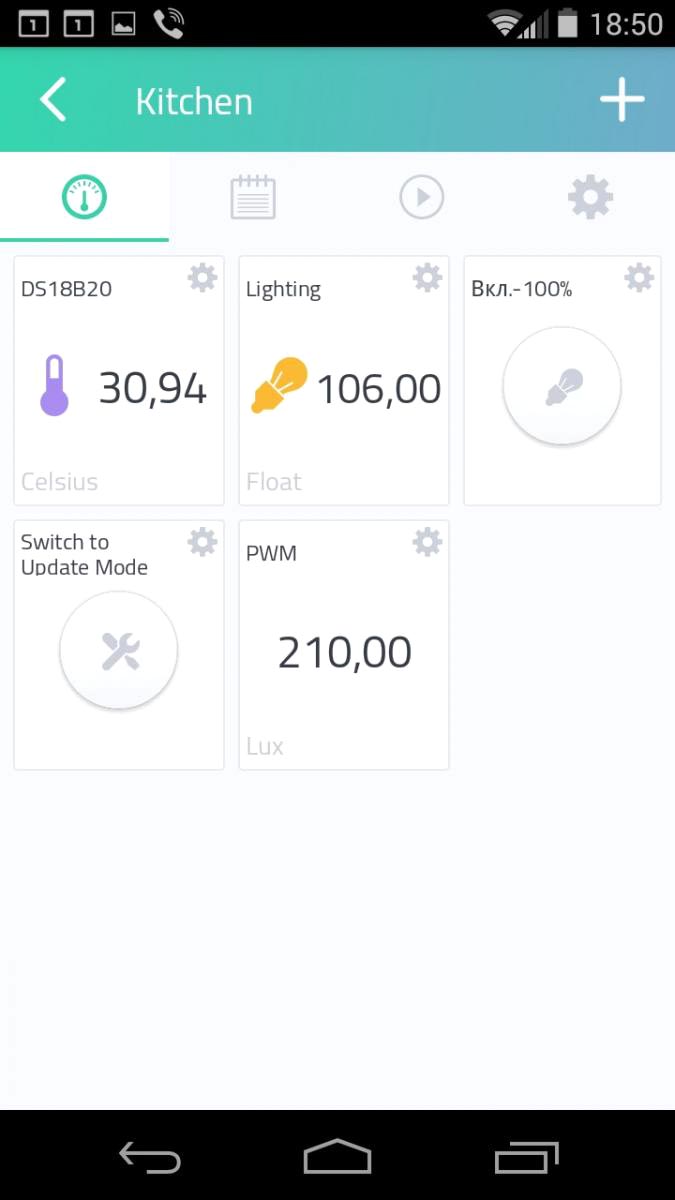
Earlier portal Radiolocman has published a description of two devices for for automatic lighting of the working area in the kitchen: Arduino version and NodeMCU version. The latter, despite several disadvantages, which I will report at the end of the article, is connected to the Cayenne and works reliably (Figure 1).
 |
|
| Figure 1. | Controller on NodemMCU for automatic lighting of the working area and monitoring parameters work well. |
In the article "Controller for automatic lighting of the working area in the kitchen. Part 2 - NodeMCU Version" I said that I plan to expand the functionality of the controller, connect additional sensors and control the kitchen hood in the kitchen. In this case, it should be noted that the "Lighting Controller" for the device on the NodeMCU was only the working title of the project, similar to the Arduino version.
One of the first tasks to be solved when extending the controller's functionality is updating the firmware. Due to the fact that the controller is located in a hard-to-reach place (on the upper cabinets of the kitchen, in my case) and connecting it to a PC or laptop via USB for firmware upgrade (without complete dismantling) is a laborious task, I decided to implement the process of updating the firmware via Wi-Fi (Over-The-Air Update, OTA Update). Connection of additional sensors and relays will not cause any difficulties, because they simply connect to pin connectors on the controller board.
For an understanding of the process of updating the ESP8266 firmware over Wi-Fi, I recommend familiarizing yourself with the main documentation and custom OTA implementation examples that can be found on the Internet. Basic conditions:
- Flash chip size is 2x the size of the sketch;
- The device and the PC from which the update is performed must be connected to the same network;
- Make sure that the firmware update process does not lead to malfunctioning of the peripherals and actuators what connected to device.
For universalization, I chose the way to update the firmware via a Web browser.
In general, all OTA implementations are functional, but in our case there is one nuance: the main application connects to the Cayenne server on startup, and when you simply add OTA functions to the application (as described in the OTA examples), the device is not working or unstable. So I had to go to the trick.
A "Switch to Update Mode" button was added to the Cayenne dashboard, when pressed, the special flag is written in the EEPROM of the controller to start the OTA after the controller is rebooted. Next, the controller is reloaded programmatically and, if the OTA start flag is set, then the server with a specific IP address (and name) on the local network is initialized. In the browser, go to the specified address and see the page where we select the binary firmware file and send it to the server. If the firmware is executed successfully, the OTA start flag is deleted in the EEPROM of the controller and the controller is rebooted. After the restart (the OTA flag is clear), the Cayenne service is initialized and the main application is executed.
Let's look at the main points.
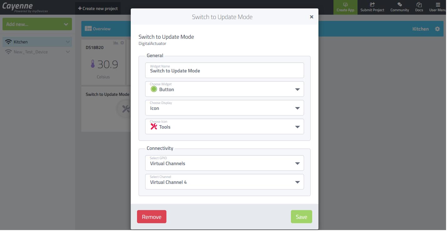
The "Switch to Update Mode" button on the Cayenne dashboard (Figure 2) is connected to Virtual Channel 4 (Virtual Pin 4). When the button is pressed (button icon changed to active) server Cayenne send transferred to the controller a value of 1. Processing of pressing the button and setting the OTA flag in the EEPROM is performed in the function CAYENNE_IN (V4) (Listing 1).
 |
|
| Figure 2. | "Switch to Update Mode" button properties in Cayenne dashboard. The button is used to switch controller in OTA mode |
Listing 1. Handling a button pressed on the Cayenne dashboard and writing OTA flag to the EEPROM.
CAYENNE_IN(V4) {
Cayenne_OTA_Button = getValue.asInt();
if (Cayenne_OTA_Button == 1) {
EEPROM.begin(4);
EEPROM.write(0, 83);
EEPROM.commit();
delay(2000);
}
}
Pay attention to the functions of working with EEPROM. The ESP8266 SoC does not have non-volatile memory, the EEPROM area (4 bytes) is allocated in the external Flash memory of the programs. The OTA flag (value 83 corresponds to the ASCII character S) is written at address 0.
In the main program loop, the state of the variable Cayenne_OTA_Button is tracked, and if it is 1, then deactivate the "Switch to Update Mode" button on the dashboard, perform a 4-second delay and resetting the controller (Listing 2).
Listing 2. Deactivating button in Cayenne dashboard and controller restart.
if (Cayenne_OTA_Button == 1) {
Cayenne_OTA_Button = 0;
Cayenne.virtualWrite(V4, Cayenne_OTA_Button);
delay(4000);
ESP.restart();
}
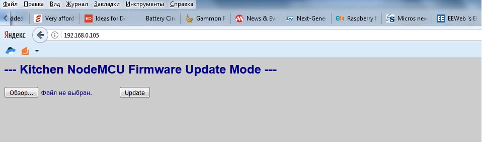
After the controller is rebooted, the setup () initialization function is executed, in which the OTA_Start_Flag is checked. If the flag is set, the server is executed and is initialized content of the web page. In the main loop (when the OTA flag is set), the server is started and a web page is generated when the client accesses (Figure 3). Also, the timer starts for 3 minutes - after this time, the OTA flag is reset, the controller is reloaded and the main application is starting (Listing 3). The availability of the server and its IP address can be found in the Serial Port monitor in Arduino IDE environment (if the device is connected to PC via USB) or in the router ARP table. Better in the settings of the router immediately register a permanent IP address for the controller (by MAC address).
 |
|
| Figure 3. | Web page generated by the controller in the OTA firmware update mode. |
Listing 3. Start the OTA server, process the connected client, and start timer to firmware update of the controller.
if (OTA_Start_Flag == 83) {
server.handleClient();
if (millis() - timeout_1 > interval_2) {
EEPROM.begin(4);
EEPROM.write(0, 70);
EEPROM.commit();
delay(1000);
ESP.restart();
}
}
We choose the firmware file (how to find the binary file compiled in Arduino IDE, I think, does not need explanations) and click the "Update" button. Update will take a few seconds, after that a message will appear in the browser about the status of the update process, the OTA flag will be reset (write to EEPROM at address 0 decimal value 70, ASCII character F), after a few seconds the controller will automatically reboot and go to the main application.
In addition, in the sketch you can specify the name of the Host device, which can be accessed in the address bar of the browser when the controller is in the firmware update mode, and this name will be displayed in the router's DHCP list. In the sketch, the name is specified as a constant:
const char* host = "ESP-Kitchen";
It should be noted that it is also possible to implement the firmware upgrade mode with additional protection by login and password.
Initially, firmware with support OTA functions is programmed into the controller in a standard way (via USB). After that, you can use the function of updating via Wi-Fi, the main thing is not to forget that the subsequent firmware (sketches) also included OTA functions. During this process, you will encounter one inconvenience, the fact is that after the first OTA update, you will need to perform a single reset of the Wi-Fi module once (on the NodeMCU the reset button). In subsequent OTA updates, everything will happen automatically. This is due to some internal registers and the architecture of the ESP8266 SoC.
 |
|
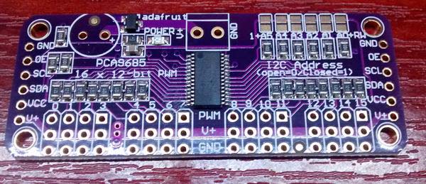
| Figure 4. | 16-channel PWM/servo driver board on PCA9685. |
Another drawback, revealed in the work of the lighting controller, is related to the software PWM implementation in the Arduino environment. At small PWM values, the pulse width of the PWM signal is unstable at the time of access to the DS18B20 temperature sensor, which is manifested by a brief and faintly blinking LED strip. Therefore, I think that it will be necessary to refrain from using software PWM in the ESP8266 in favor of the widespread 16-channel PCA9685 PWM chip or the expansion board based on it using the I2C control interface (Figure 4).
Downloads
- Arduino Sketch for Controller for automatic lighting with OTA - download
References
- Cayenne dashboard simplifies IoT project building on Raspberry Pi
- Controller for automatic lighting of the working area in the kitchen. Part 1 - Arduino Version. Schematic, Sketch and PCB
- Controller for automatic lighting of the working area in the kitchen. Part 2 - NodeMCU Version. Schematic, PCB, Sketch
- All project files for the backlight controller on NodeMCU