Tom Bruhns
EDN
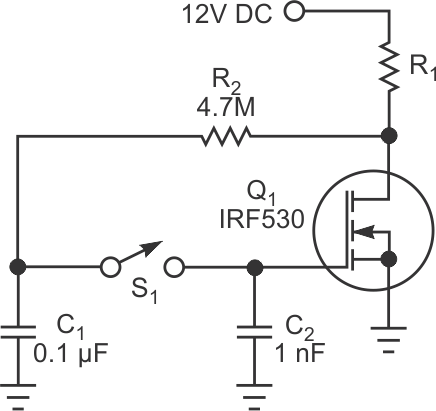
The novelty circuit in Figure 1 illustrates the extremely low gate-leakage current typical of modern power MOSFETs. You can find parts that, in a moderately dry environment, will hold their state for days at a time. In operation, if MOSFET Q1 is off, the load – perhaps a lamp or a buzzer – pulls Q1’s drain to nearly the 12 V-dc power-supply voltage. R2 charges C1 to practically the same voltage. If you tap momentary-contact switch S1, C2 and the gate of Q1 charge to about 99% of C1’s initial voltage, assuming that the tap is short enough that C1 doesn’t discharge significantly back through R2 to the drain of Q1, which is now at a low voltage. During the next couple of seconds, C1 discharges through R2 toward the new drain voltage of Q1, which now conducts current through load resistor R1.
 |
||
| Figure 1. | This “toggle” circuit demonstrates the low gate leakage of modern power MOSFETs. |
|
In the construction of the circuit, you must ensure extremely low leakage from the MOSFET’s gate node. You can omit C2 if you use a switch with essentially no leakage, and you may find that the gate capacitance of Q1 is enough and that the leakage is low enough that days pass before the output changes significantly. If you’d like to ensure a longer hold time, you can increase the value of C2. A modern polypropylene capacitor should have a self-discharge time constant measured in years if you keep it clean, dry, and not too far above room temperature. If you increase C2, proportionately increase C1 and decrease R2 to maintain an R2C1 time constant of about half a second.
Another curious behavior of this novelty circuit occurs if you hold down S1 for a few seconds. The gate of Q1 then goes to a voltage slightly higher than the gate’s threshold voltage for Q1. If, for example, the power supply is 6 V and the load is a 6 V incandescent lamp and Q1’s gate threshold is approximately 3 V, the lamp will light dimly. When you release the switch, because a typical power MOSFET has a high rate of drain-current change with gate-voltage change – that is, transconductance – you can observe the slow change in gate voltage as a change in lamp brightness. Any leakage is inside and external to Q1. You may be able to detect a change in lamp brightness within a few seconds. But, even if you don’t notice it, some change of voltage will occur. If you tap S1 several times at intervals of a few seconds, the lamp will soon toggle between full brightness and fully off.
 |
||
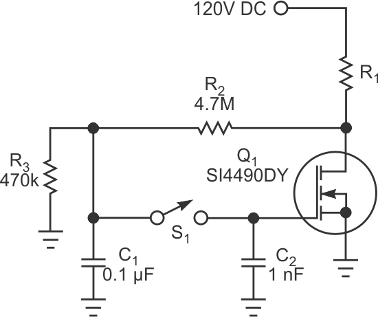
| Figure 2. | This circuit can control higher voltages because it supplements R2 with a resistor to ground to form a voltage divider, ensuring that C1 doesn’t charge to a voltage that would destroy the gate of Q1. |
|
To use the circuit to control higher voltages, you can supplement R2 with a resistor to ground to form a voltage divider to ensure that C1 doesn’t charge to a voltage that would destroy the gate of Q1 (Figure 2). For a more practical toggle circuit that will indefinitely hold a state, you can add a transistor and some resistors (Figure 3).
 |
||
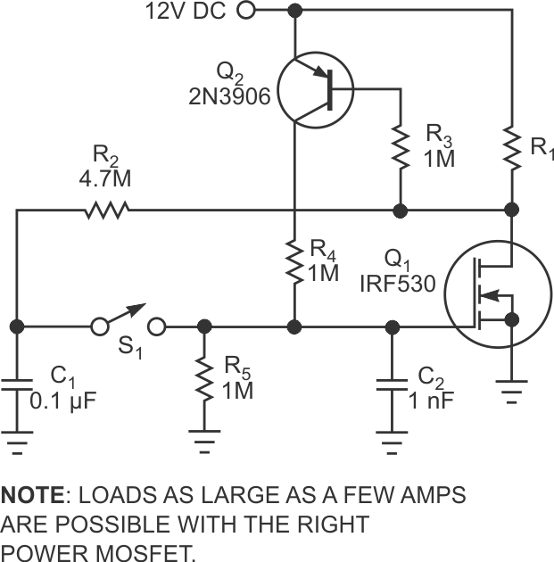
| Figure 3. | This version of the toggle circuit indefinitely holds a state. | |
If Q1 is on and powers the load, then Q2 is also on, holding Q1’s gate on at about half the power-supply voltage because of the voltage-divider action of R4 and R5. Tapping S1 toggles the output as before, and, with Q1 off, Q2 is also off, allowing R5 to hold Q1’s gate near ground potential.
