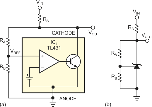
Developed as a three-terminal shunt regulator, the popular and multiple-sourced TL431 IC offers designers many intriguing possibilities beyond its intended application. Internally, the TL431 comprises a precision voltage reference, an operational amplifier, and a shunt transistor (Figure 1a). In a typical voltage-regulator application, adding two external resistors, RA and RB, sets the shunt-regulated output voltage at the lower end of load resistor RS (Figure 1b).
 |
|
| Figure 1. | Despite the block diagram, the TL431 is internally complex (a), but you need only three external resistors to use the TL431 in a basic shunt-regulator circuit (b). |
In today's power-supply market, cost reduction drives most designs, as evidenced by Asian manufacturers that have resorted to shaving pennies off their power-supply products by using single-sided pc boards. This Design Idea shows how a three-terminal shunt regulator can replace a more expensive conventional operational amplifier in a power-converter design.
A switched-mode power supply uses a galvanically isolated feedback portion of a PWM circuit (Figure 2). In designs that omit a voltage amplifier, a shunt regulator can serve as an inexpensive op amp. Resistors RI and R set the power supply's dc output voltage, and optocoupler IC2 provides galvanic isolation. Resistor R1 provides bias for the optocoupler and the TL431, IC1. Resistor R3 and zener diode D1 establish a fixed bias voltage to ensure that bias resistor R1 does not form a feedback path. Resistors R1 and R2 control the gain across the optocoupler. In most designs, the ratio of R2 to R1 is roughly 10-to-1.
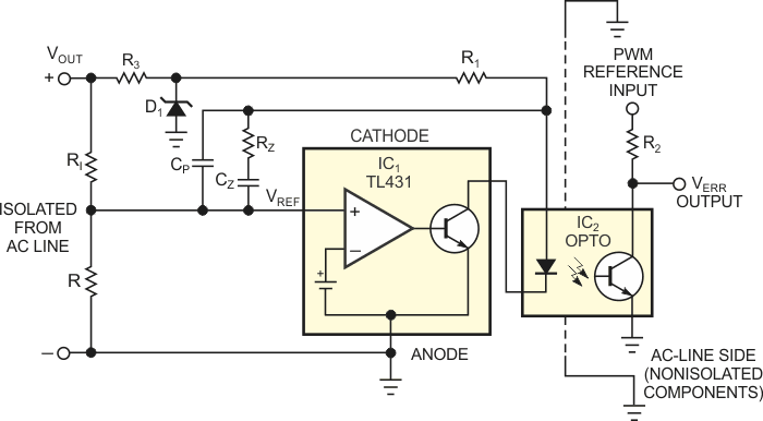 |
|
| Figure 2. | A TL431 replaces a more expensive operational amplifier in this power supply’s PWM feedback- regulator circuit. |
Components CP, CZ, and RZ provide frequency compensation for the control loop. The optocoupler includes a high-frequency pole, fP, in its frequency response, an item that most optocouplers' data sheets omit. You can use a network analyzer to determine the location of the high-frequency pole or estimate that the pole occurs at approximately 10 kHz. The following equation describes the compensation network's small-signal transfer function:
Note that, under some circumstances, adding a bypass capacitor across diode D1 may be necessary for output-noise reduction.