PWM is a simple, cool, cheap, cheerful, and (therefore) popular DAC technology. Excellent differential nonlinearity (DNL) and monotonicity are virtually guaranteed by PWM. Also guaranteed are a stable zero and a full-scale accuracy that’s generally limited only by the quality of the voltage reference. However, PWM’s integral nonlinearity (INL) isn’t always terrific, and the necessity for low-pass filtering-out of ripple means its speed isn’t too swift either. These messy topics are covered in…
- A common cause of, and a software cure for, PWM INL is discussed here in “Minimizing passive PWM ripple filter output impedance: How low can you go?” (Ref. 1)
- The slow PWM settling times (TS) that can be problematic, together with a way to reduce them, are addressed here in “Cancel PWM DAC ripple with analog subtraction.” (Ref. 2)
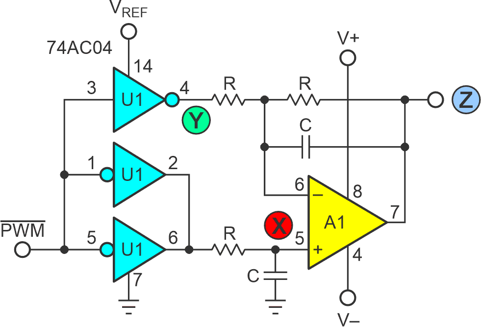
Figure 1 offers a tricky, totally analog strategy for both. The ploy in play is Take Back Half (TBH). It relies on two differential relationships that effectively subtract (take back) the error terms.
- For signal frequencies less than or equal to 1/TS (including DC) XC >> R and Z = 2(XAVG – YAVG/2).
- For frequencies greater than or equal to FPWM, XC << R and Z = XRIPPLE – YRIPPLE.
 |
|
| Figure 1. | All Rs and Cs are nominally equal. The circuit relies on two differential relationships that effectively subtract the error terms for the TBH methodology. |
Because only one switch drives load R at node Y while two in parallel drive X, INL due to switch loading at Y is exactly twice that at X. Therefore, Z = 2(XAVG – YAVG/2) takes back, cancels the error, and has (theoretically) zero INL.
XRIPPLE = YRIPPLE, so Z = XRIPPLE – YRIPPLE = 0 nulls it out, has likewise (theoretically) zero ripple, and ripple filter RC time constants can be made faster and settling times shorter.
The DC conversion component at Z = -PWM_duty_factor×VREF. Conversion accuracy is precisely unity, independent of resistance and capacitance tolerances. However, they ideally should be accurately equal for best ripple and nonlinearity cancellation.
References
- Woodward, Stephen. "Minimizing passive PWM ripple filter output impedance: How low can you go?"
- Woodward, Stephen. "Cancel PWM DAC ripple with analog subtraction."