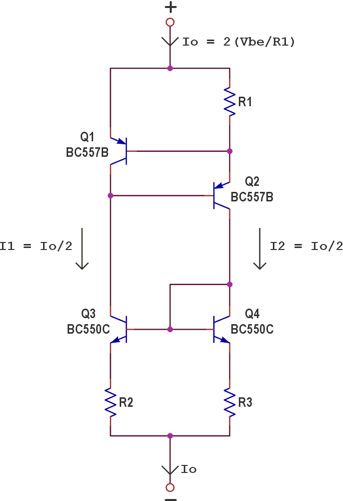
The circuit in Figure 1 combines a VBE-referenced current source with a current mirror to implement a simple two-terminal, fully floating LED current sink or source. This approach is well-suited for applications in which tight current accuracy is not required, such as driving LED strings where a 5–10% current tolerance is acceptable.
 |
|
| Figure 1. | A simple, fully floating LED current driver based on a VBE-referenced current source and a BJT current mirror. The circuit operates as either a current sink or source and supports output currents up to 100 mA. Note: R2 = R3. All resistors are ¼ W and 5%. |
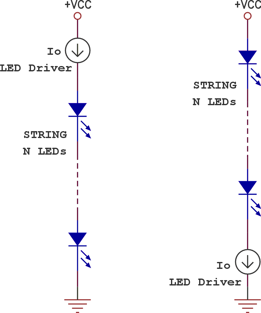
The LED driver can drive an arbitrary number of series-connected LEDs, provided the available supply voltage is at least 2.3 V. The topology supports both high-side and low-side operation, as shown in Figure 2. Output current ranges from a few milliamps up to 100 mA, with no requirement for heat sinks.
 |
|
| Figure 2. | High-side and low-side operating configurations enabled by the fully floating nature of the LED driver. |
The current source formed by BJTs Q1 and Q2 is set by resistor R1. A current mirror implemented with BJTs Q3 and Q4, using equal emitter resistors (R2 = R3), forces nearly equal currents in branches I1 and I2, as long as the voltage drop across the emitter resistors is at least 0.5 V. This requirement helps compensate for VBE mismatch between the transistors. The total LED current is therefore doubled, while power dissipation is evenly shared among the devices.
Experimental data (Table 1) confirm the expected behavior: output current scales with R1, and the minimum supply voltage increases from 2.3 V at 9.3 mA to 2.8 V at 97 mA, consistent with the headroom required by the VBE-referenced source and mirror.
| Table 1. | Experimental data showing R1, R2/R3, and corresponding output current and minimum supply voltage |
||||||||||||||||||||
|
|||||||||||||||||||||
With a minimum operating voltage of approximately 2.8 V, the circuit dissipates about 280 mW at a maximum output current of 100 mA. Higher supply voltages reduce efficiency due to increased power dissipation in the driver.
Because the LED current is VBE-dependent, it exhibits temperature sensitivity, with a temperature coefficient of approximately –0.3 %/°C. Using a resistor with a negative temperature coefficient for R1 can partially compensate for this effect.