There are many circuits published showing zero-crossing detectors for use with 50- and 60-Hz power lines. Though the circuit variations are plentiful, many have shortcomings. This Design Idea shows a circuit that uses only a few commonly available parts and provides good performance with low power consumption.
In the circuit shown in Figure 1, a waveform is produced at with rising edges that are synchronized with the zero crossings of the line voltage, VAC. The circuit can be easily modified so that it produces a falling-edge waveform that is synchronized with VAC.
 |
||
| Figure 1. | The zero-crossing detector uses few components and consumes very little power. The VO signal has a rising edge that is coincident with each zero crossing of the line voltage, VAC. |
|
The circuit operates as follows. At the zero crossings of VAC, the current through the capacitor and the LED of the HCPL-4701 optocoupler satisfies Equation 1 below. Equation 2 shows the standard conversion between radians per second and hertz; it also shows the derivation and explanation for VI(t). Equations 3 and 4 show the simplification used in Equation 1. Because the voltage across the LED is close to constant, differentiation of that value with respect to time results in a zero value.
 |
(1) |
where
and
 |
(2) |
 |
(3) |
because
 |
(4) |
(VLED » constant).
The peak value of the current through the LED is a function of the capacitor, C, so you must choose a value for C under the constraint that at the initial time (t = 0) and for a given minimum supply-voltage value, the intensity exceeds the triggering threshold value for the optocoupler. In the case of the HCPL-4701, it is IF(ON) = 40 μA.
Diode D1 not only allows for the capacitor to discharge but also prevents the application of a reverse voltage on the LED. The maximum reverse input voltage of the HCPL-4701 is 2.5 V.
Resistor R1 is included in order to discharge the energy stored in the capacitor in the latter portion of each cycle of VI(t) when IC(t) < 0 (Figure 1). Its maximum value is limited by the capacitor, by the peak value of the supply voltage (VAC-PEAK), and by the maximum acceptable time delay of the current rising edges through the LED with respect to the corresponding ac-voltage zero crossing (Figure 2). Its minimum value is limited by the maximum allowable power dissipation in R1
 |
||
| Figure 2. | The relationship between VI(t) and ILED(t) is a function of the value of R1. The time delay between the zero crossing and the LED current is shown. |
|
A practical compromise has to be reached.
Table 1 shows the time delay (tDELAY) of the current rising edges through the LED and the power dissipation for three different values of R1. Notice that the time delay of the rising edges of VO with respect to the zero crossings of VAC must include an additional delay for the optocoupler’s propagation time delay. The HCPL-4701 has a typical propagation time delay of 70 μsec.
| Table 1. | iLED time delay for different values of R1 | ||||||||||||
|
|||||||||||||
Based on the previous information, the following practical values for C and R1 are obtained:
- For VAC = 230 VRMS±20% (Figure 3): C = 0.5 nF/400 V (MKT-HQ 370 polyester metallized, MKT series), R1 = 560 kΩ/0.25 W, tDELAY = 114 μsec (the time delay in the rising edges of VO with respect to the zero crossings of VAC), and P ≈ 100 mW (average power from the ac line).
 |
||
| Figure 3. | Empirical results are shown for VAC = 230 VRMS, C = 0.5 nF, and R1 = 560 kΩ. |
|
- For VAC = 115 VRMS±20% (Figure 4): C = 1 nF/200 V, R1 = 220 kΩ/0.25 W, tDELAY = 130 μsec (time delay in the rising edges of VO with respect to the zero crossings of VAC), and P ≈ 65 mW (average power from the ac line).
 |
||
| Figure 4. | Empirical results are shown for VAC = 115 VRMS, C = 1 nF, and R1 = 220 kΩ. | |
- For operation from 80 to 280 VRMS: C = 1 nF/400 V and R1 = 330 kΩ/0.25 W.
 |
||
| Figure 5. | Empirical results are shown for VAC = 267 VRMS, C = 1 nF, and R1 = 220 kΩ. | |
Empirical results are shown for VAC = 267 VRMS, C1 = 1 nF, and R1 = 220 kΩ (Figure 5). See Figures 6 and 7 for additional empirical results.
 |
||
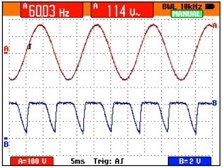
| Figure 6. | Empirical results are shown for VAC = 114 VRMS, C = 1 nF, and R1 = 560 kΩ. |
|
Note that as with any device connected directly to the mains, exercise extreme caution while bench testing the circuit. Follow proper guidelines when laying out a printed circuit board.
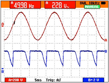 |
||
| Figure 7. | Empirical results are shown for VAC = 228 VRMS, C = 1 nF, and R1 = 560 kΩ. |
|