The Geiger counter is a pretty simple device to detect radiations. Many forms of radiations from radio elements (alpha, beta, gamma) can be detected but it is more sensitive to beta and gamma radiations. The Geiger-Muller tube is a simple device, it's a tube filled with a gas with two electrodes. A high potential is applied betweens electrodes. When a ionizing particle arrived, it create a temporary conductive path between electrodes. The resulting current can be detected by an electronic amplifier.
A Geiger counter is composed of a high voltage generator, a geiger tube, an amplifier and a monostable. The following schematic show clearly these 4 parts. In the second part of this article will show how to connect this counter to a USB microcontroler and a computer.
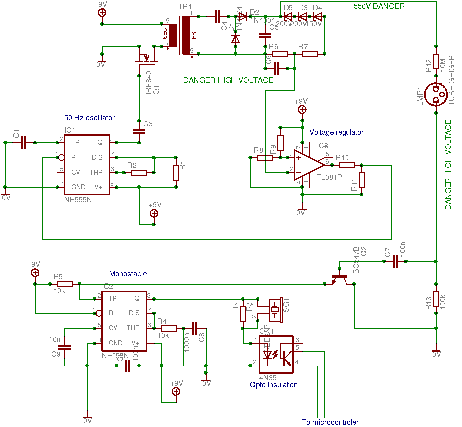
Click for high resolution schematic
The high voltage generator
Warning! High voltage is dangerous, you have to be very very careful during your experimentation. Never touch any part of the circuit. Always turn off the power before to manipulate the circuit. Be careful even with power turned off, a high potential can be present in condensers C4/C5.
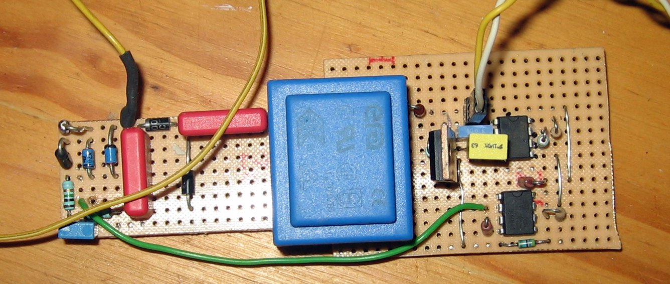
The generator is composed of a 50 Hz oscillator with a classical NE555 circuit, a transformer, a voltage multiplier and a voltage regulator. When the potential is too high, the regulator stop oscillations in the oscillator. The voltage is also limited by zener diodes at 550 V.The transformer is a classical 9 V/220 V but we use the primary to produce a medium voltage before the voltage multiplier.It's possible to use a high impedence voltmeter to control the tension or a "tension tester screedriver" after the transformer.
The Geiger tube
The tube can be found for few Euros /dollars on ebay. Many kind of tubes can be used, but the voltage should be adjusted to the characteristic of the tube. Usually 550-600 V is used. The current in the tube is limitate by a 10 MOhm resistor, but it's better to use 2*4.7 MOhm in serial or a resistor certified for high voltage.
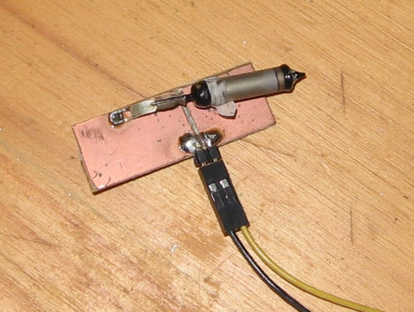
Be careful, the high voltage is connected to the tube. Never touch it.
The amplifier and monostable
A simple transistor is used to amplify the signal from the tube. Then the emitter of the transistor is connected to a 555 circuit in monostable configuration. A very short impulsion will be enough to start the monostable. The exit of the 555 is connected to a buzer to produce the traditional sound 'tac tac' of a geiger counter. The exit can also be connected to leds or an optocoupler to connect the entry of a microcontroler.
Any part of the circuit before the optocoupler can be dangerous - never touch it!
Microcontroler connexion
The output of the optocoupler can be connected to a microcontroleur with USB capability. The USB experimentation board describe on this site is perfectly suitable. Here is a picture of my experimentation circuit. The USB card is connected to the computer.
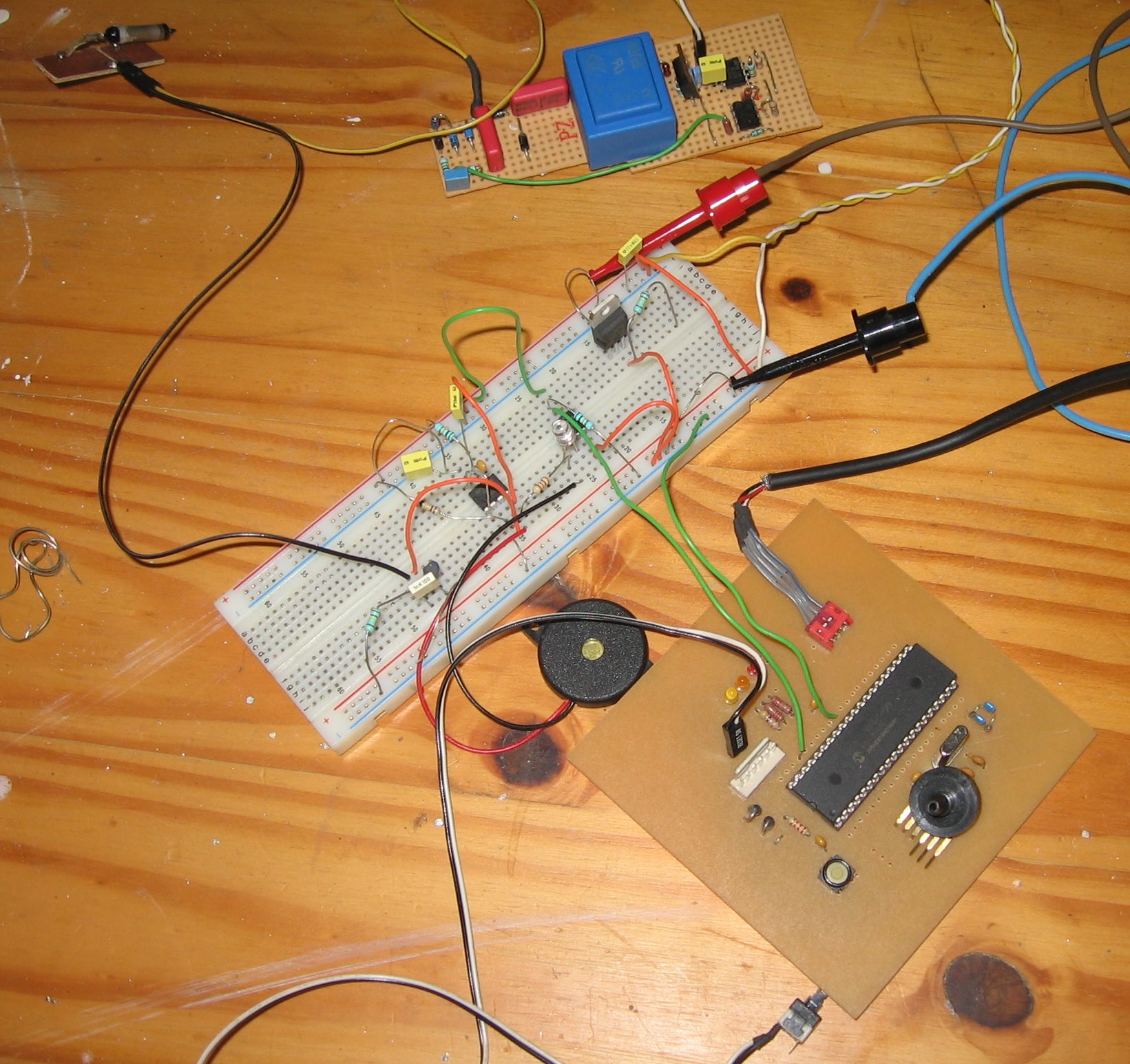
Now you can modify the firmware of the USB to send data any time the counter send an impulsion. It's possible to measure time between two impulsions directly with the pic or with the computer program.
You can modify the user.c program used in the USB tutorial to check the status of the connected pin of the microcontroler
if(mUSBUSARTIsTxTrfReady()) { while( PORTCbits.RC2); mUSBUSARTTxRam("Impulsion"); start_up_state=0; }
Then in the computer, you can calculate the average time between impulsions or to graph data to eventuality detect some anomaly.