Incremental-rotation or linear encoders are very common, but normally they do not provide a direction signal. This design shows an easy way to detect forward or reverse direction.
Incremental encoders normally provide two output signals, usually named Channel A and Channel B. These signals deliver both clock information, depending on resolution, and rotating speed. They differ only in phase margin (for example, –90° for clockwise and +90° for counter clockwise).
The circuit in Figure 1 uses these signals as inputs to a 4538 single-chip, dual monostable multivibrator. Depending on the speed required for the application, the IC could be a metal-gate device, a 74HC, or a 74HCT type.
 |
||
| Figure 1. | The direction discriminator circuit is based on a dual monostable multivibrator, which can be a metal-gate, 74HC, or 74HCT type depending on the speed required by the application. |
|
The feedback from one of the outputs to an input is used to avoid re-triggering. This isn’t strictly necessary but helps to keep the pulse duration constant. On the other hand, an important function is to trigger forward pulses from one edge of the input signal and reverse pulses from the other edge of that signal (Fig. 2).
 |
||
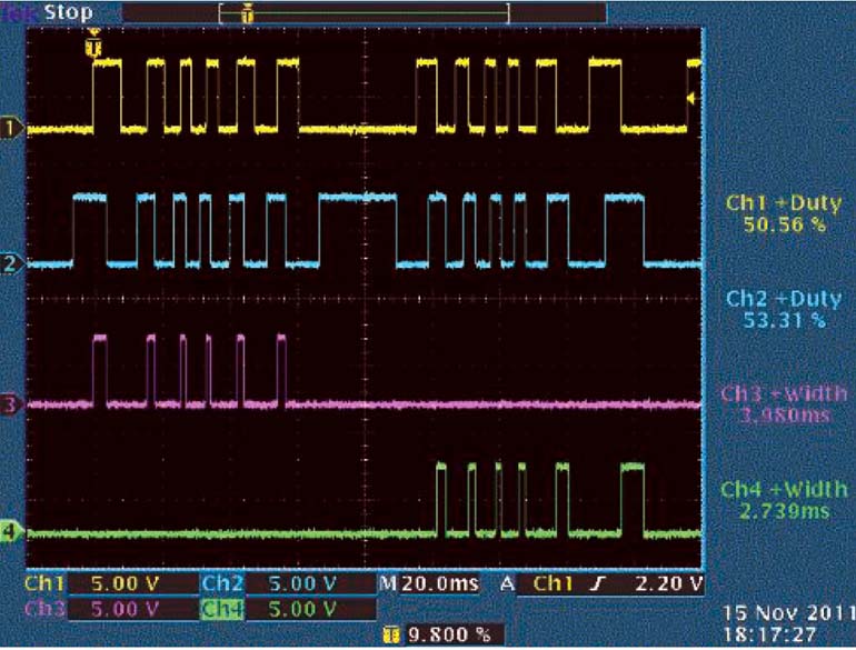
| Figure 2. | This scope printout shows the behavior of the circuit when the encoder shaft is moved a little between clockwise and counter-clockwise. Channel 1 is In Channel A (U1 pin 4). Channel 2 is In Channel B (pin 13). Channel 3 is Out Forward (pin 6). Channel 4 is Out Reverse (pin 10). |
|
This is why the same mechanical position, or slot edge of the encoding wheel, delivers, for instance, a positive edge in the forward direction and a negative edge in reverse. So if a design uses the same electrical edge for triggering, the result will be a hysteresis in changing the direction of one encoder slot width, which is normally one half of the rated encoder resolution (Fig. 3). This can create accuracy problems that get even worse if the encoder is mechanically jittering (vibrating) around the clocking edge.
 |
||
| Figure 3. | This circuit using a D flip-flop can cause inaccuracies at the point of reversing the direction, especially when the encoder is jittering (vibrating) around the clocking edge. |
|
The designer should use care in determining the output pulse duration of the monostables. If medium scale integrated (MSI) logic counters like the ’193 are used, 200 ns will be enough, but sometimes a microprocessor using its interrupt inputs counts the forward and reverse signals. This requires a pulse length of at least the maximum MCU interrupt response time.
In many cases, this may be pulse lengths of some tens of microseconds as in the circuit of Figure 1, where the pulse width, tPLS ≈ 50 µs. Once the pulse length is known, the maximum speed is determined by:
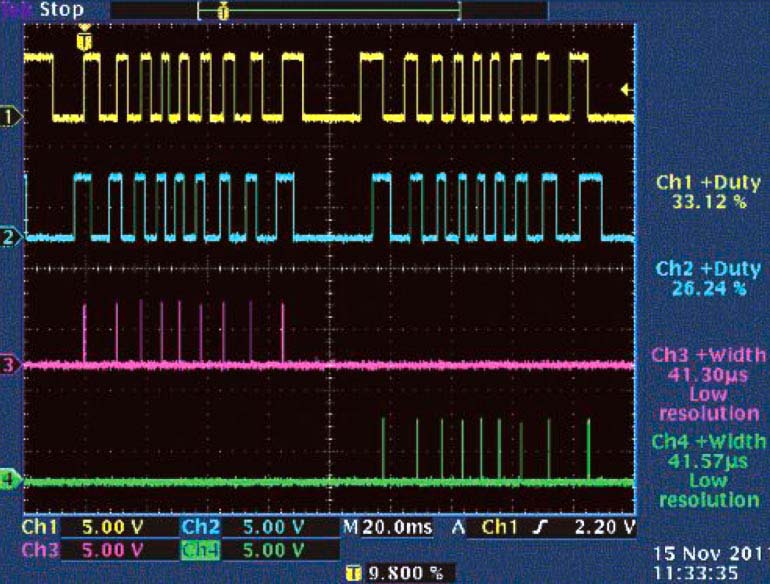
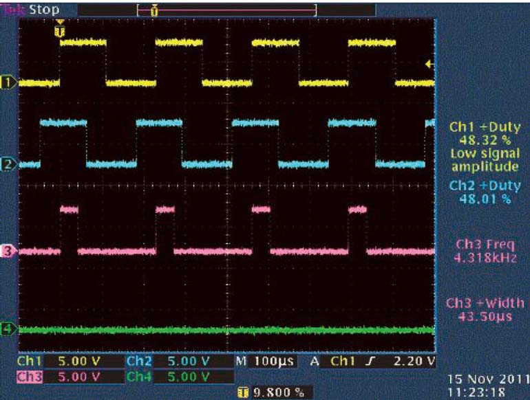
So, the maximum speed or encoder frequency in this example is approximately 5 kHz (Fig. 4). The circuit won’t totally stop working if overdriven in frequency, but beyond the maximum frequency the duration of the output pulse will be cut to a length from the triggering edge (Channel A) to the falling edge (Channel B).
 |
||
| Figure 4. | These scope traces show the circuit’s response when the encoder’s shaft turns clockwise at near maximum speed. The channels are the same as in Figure 2. |
|
 |
||
| Figure 5. | Resistors R1 and R2 in the direction discriminator circuit can be removed with only minor changes to the circuit’s response. Again, the scope’s traces are the same as those in Figure 2. |
|
This leads to a possible simplification of the circuit in Figure 1. If you eliminate resistors R1 and R2, the output pulse would always be the time from the triggering edge of Channel A to the falling edge of Channel B (Fig. 5).