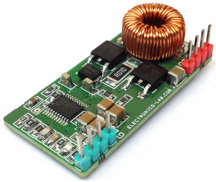
This module is a non-isolated 7 A DC-DC converter. The module can convert any DC voltage between 7 V to 50 V to a 5 V DC with load current up to 7 A (Figure 1). The project has been designed around LM5116 Wide Range Synchronous Buck Controller IC. The design includes 6uH toroid inductor and two N channel MOSFETS (Figure 2). The operating frequency is 250 kHz.
 |
|
| Figure 1. | 50 V to 5 V/7 A Synchronous Buck (Step-down) Converter. |
Features:
- Wide Operating Range 7 V – 50 V
- Output 5 V DC
- Load Current Up To 7 Amps
- Thermal Shutdown
- Operating Frequency 250 kHz
- PCB Dimensions 45.04 mm x 22.82 mm
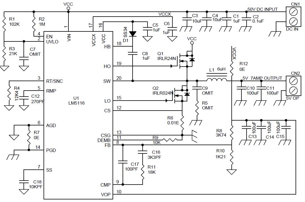
Synchronous Buck (Step-down) Converter Schematic Diagram shown in Figure 2. The list of used components is given in the Table 1.
 |
|
| Figure 2. | 50 V to 5 V/7 A Synchronous Buck (Step-down) Converter Schematic Diagram. |
The LM5116 is a synchronous buck controller intended for step-down regulator applications from a high-voltage or widely varying input supply. The control method is based upon current mode control utilizing an emulated current ramp. Current mode control provides inherent line feed-forward, cycle-by-cycle current limiting, and ease-of-loop compensation. The use of an emulated control ramp reduces noise sensitivity of the pulse-width modulation circuit, allowing reliable control of very small duty cycles necessary in high-input voltage applications.
The operating frequency is programmable from 50 kHz to 1 MHz and the LM5116 drives external high-side and low-side NMOS power switches with adaptive dead-time control. A user-selectable diode emulation mode enables discontinuous operation mode, for improved efficiency at light load conditions. A low quiescent current shutdown disables the controller and consumes less than 10 µA of total input current.
Additional features include a high-voltage bias regulator, automatic switch-over to external bias for improved efficiency, thermal shutdown, frequency synchronization, cycle-by-cycle current limit, and adjustable line under-voltage lockout. The device is available in a power enhanced HTSSOP-20 package featuring an exposed die attach PAD to aid thermal dissipation.
| Table 1. Part List. | ||||||||||||||||||||||||||||||||||||||||||||||||||||||||||||||||||||||||||||||||||||
|
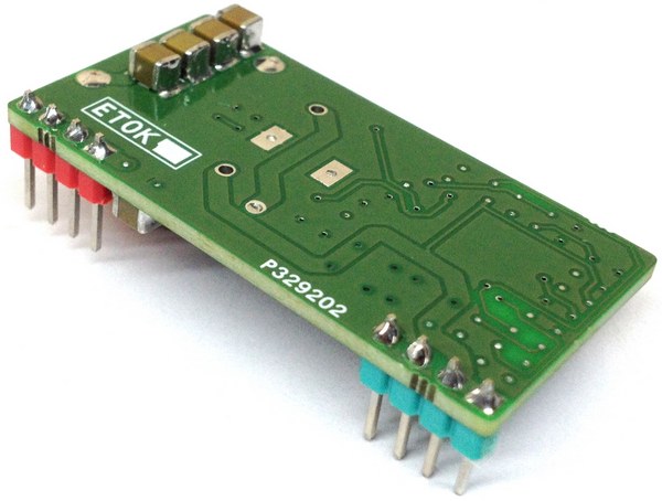
PCB photos shown in Figure 3. Converter Module Connections shown in Figure 4.
|
|
 |
|
| Figure 3. | 5V/7A Synchronous Buck (Step-down) Converter PCB photos. |
|
|
| Figure 4. | 50 V to 5 V/7 A Synchronous Buck (Step-down) Converter Connections. |