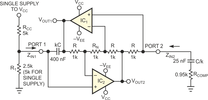
The circuit in Figure 1 is based on a classic GIC (generalized impedance converter). The sine-wave-oscillator circuit has inherent amplitude stabilization and normally operates from dual power supplies. However, if you connect an additional resistor, RCC, to VCC, you can operate the circuit with one supply (with VEE = 0 V). You can adjust the oscillation frequency by varying R1. RCOMP ensures oscillation and does not affect the oscillation frequency. The remaining passive components are four equal-value resistors, R, and two capacitors, kC and C/k, where k is a scaling factor. This modification of the classic GIC structure incorporates an additional resistor, RN, between both inverting op-amp inputs. The GIC topology has excellent high-frequency properties and thus finds extensive use in active-filter circuits. The GIC structure can simulate a grounded inductance or a grounded FDNR (frequency-dependent negative resistance).
 |
|
| Figure 1. | A GIC-based resonator provides inherent amplitude control and low distortion. |
You can explain the function of the circuit by starting with the GIC input impedance at either Port 1 or Port 2. A straightforward analysis of the circuit yields the input impedance at Port 1:
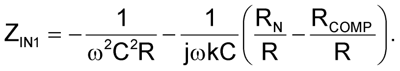
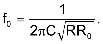
Note that, for RCOMP = RN, the expression for ZIN1 represents the input impedance of an ideal FDNR. The FDNR, together with an ohmic shunt resistance from Port 1 to ground, forms a tuned circuit with the inherent capability to oscillate. In reality, however, the oscillation would die out because of parasitics arising from lossy capacitors and imperfect amplifiers. The circuit in Figure 1 compensates for these losses by using the second portion of ZIN1, representing a negative capacitance for RCOMP < RN. In practice, you should choose RN = R and a resistor ratio, RCOMP/R, close to unity (for example, RCOMP/R = 0.95 to 0.98). If you perform the analysis at Port 2 of the circuit, the input impedance, ZIN2, represents an ideal inductance in series with a negative resistor. Shunting this impedance with a capacitor-resistor branch (C/k and RCOMP in Figure 1) creates a lossless LC tank circuit. This tank circuit can oscillate if you satisfy the condition RCOMP < R. The circuit starts reliably and oscillates at the following frequency:
For the circuit values in Figure 1, IC2 saturates, providing a clipped sinusoidal signal at VOUT2. VOUT1 is a filtered version of that signal. Thus, no extra circuitry is necessary for amplitude stabilization. However, the quality of the sinusoidal signal at VOUT1 depends on the Q factor of the resonator circuit, as the following equation states:
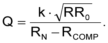
For the values shown, a quality factor Q > 100 results with a capacitance scaling factor k = 4, C = 100 nF, and (RN – RCOMP) = 50 Ω. VOUT1 provides a signal with a total harmonic distortion lower than 1% at f0 = 1 kHz. The peak-to-peak amplitude of the sinusoidal signal is approximately 1 V lower than the total supply-voltage span.