The advent of inexpensive standardized 16- and 24-bit audio I/O hardware for personal computers inspired a rush of oscilloscope simulating applications. Many of these “Sound Card Scopes” are quite capable, providing input scaling, triggering and timebase options, frequency analysis, data file storage, and built-in signal generators.
But even the best software app can go only so far to overcome the basic limitations of hardware that was, after all, specifically optimized for audio acquisition and reproduction while being as cheap as possible. Among those limitations are:
- Inconveniently low input impedance: Usually no more than 10 kΩ to 30 kΩ and therefore likely to excessively load the signal source.
- Limited input range: Fixed at ~5 Vpp with permanent damage likely (possibly even to the connected computer) if this span is significantly exceeded.
- Bandwidth restrictions: On the high end to ~20 kHz; and 10 Hz, 20 Hz, or even 100 Hz on the low.
In response, many hardware remedies have appeared in the literature. Basic buffers and variable attenuators are available that improve input impedance and range, while an ingenious design based on the AD583 S&H [1], stretched the upper bandwidth limit (for repetitive waveforms) to 50 MHz!
This Design Idea for a sound card scope front end is a little different. Referring to the schematic (Figure 1), it combines megohm input impedance with switched x1-x10-x100 attenuation, but then adds extension of the bottom end of sound card bandwidth by more than a factor of 10. For dual-channel (stereo sound card) scopes, the circuit is simply duplicated.
 |
|
| Figure 1. | Sound card oscilloscope front end schematic. |
The front end begins with the cascaded resistor network around attenuator switch S1. It provides 1 MΩ (minimum) input impedance and selectable decade attenuation without using resistors higher than 2 MΩ (the point where precision resistors start to become expensive), with a simple ON–OFF–ON three position toggle switch.
The non-inverting 9051 buffer amplifier level shifts the incoming signal to VDD/2, and applies adjustable (one-time calibration for the particular sound card hardware being used) low frequency correction via the C1(R1+R2) feedback network. This is how that works.
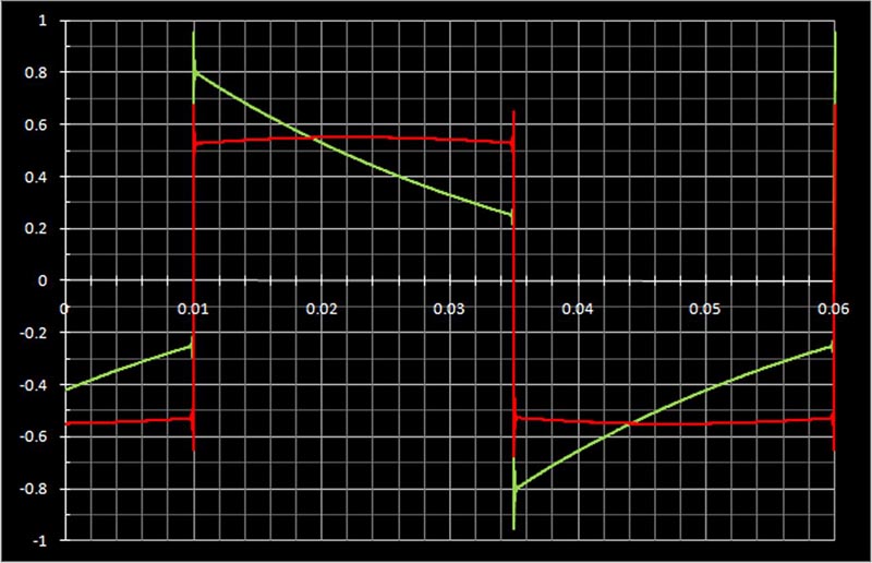
Essentially all sound card CODECs have AC coupled inputs, and even though the rated cutoff frequency of the associated RC time constant may be as low as 10 Hz (as was the case for the CODEC used to record the green trace shown in Figure 2), the resulting distortion (“droop”) of common waveforms of interest (e.g., Figure 2’s 20 Hz square wave), can be extreme and unacceptable.
The fix consists of adjusting (R1+R2) so that the feedback time constant equals and cancels that of the CODEC input: 22 ms in this example. With this one-time calibration in hand, a typical improvement is shown by the red trace in Figure 2, producing a quantitatively accurate reproduction of the original waveform, and of all similar inputs. Compensation isn’t quite perfect, because eventually the 9051 will run out of headroom, and because CODEC high-pass filtering is sometimes more complex than a simple single-pole RC. But as Figure 2 illustrates, the improvement is significant and useful.
 |
|
| Figure 2. | Low frequency response correction, showing the uncorrected CODEC response (green) versus the corrected response (red) with R1 adjusted for 22 ms RC. |
Of course, as we add endless enhancements to what began as ubiquitous, simple, cheap, and cheerful sound card hardware, eventually there must come a point where the proverbial lily has been over-gilded and its cost effectiveness has been lost. Hopefully this design doesn’t cross that line.