Before running a formal test with multiple resistance temperature detector (RTD) sensors, it is often necessary to calibrate and debug a data-acquisition system to verify basic functionality. The brute-force approach would be to wire all the sensors to the front-end board and use an environmental chamber to set the temperature of the RTDs. An easier way is to use a software-controlled RTD emulator to produce voltages that span the range of the RTD’s output.
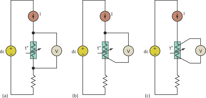
RTD sensors are available using two-, three-, and four-wire configurations, which differ in their use of sense wires (Fig. 1a, 1b, and 1c, respectively). The most basic type of RTD has two wires and no sense wire, while the three-wire RTD has one sense wire attached directly to the RTD lead, and the four-wire RTD has two sense wires.
 |
|
| Figure 1. | In the various RTD wiring configurations (two-, three-, and four- wire), the use of extra sense wires increases precision by reducing errors induced by cable resistance, but at a cost in extra leads. |
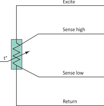
The extra sense wires are used to minimize the effects of parasitic resistance, which occurs when using long cables and reduces the achievable precision of sensor readings. Four-wire RTDs offer the highest precision, but are the most expensive (Fig. 2). The RTD excite wire is connected to constant-current source, and return wire is typically connected to a load resistor.
 |
|
| Figure 2. | Nomenclature for the RTD sensor wires maintains consistency, regardless of the number of wires used. |
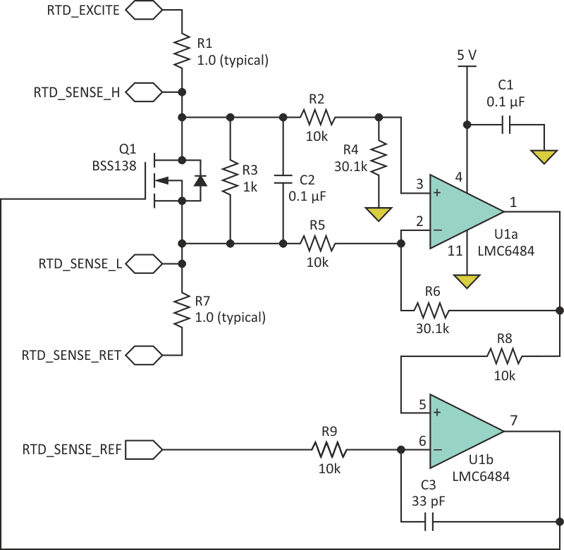
This emulator supports all three RTD configurations (Fig. 3). It uses an external current source and load resistor provided by the external sensor board to emulate characteristics of real RTD device. The constant-current source should have relatively low current to prevent self-heating of the RTD sensor. It is usually selected to be in the range of few hundred microamps to 1 mA. Readings are usually done via an instrumentation amplifier followed by a 12- to 16-bit analog-to-digital converter (ADC).
 |
|
| Figure 3. | In the RTD emulator, Q1 (an N-channel logic-level enhancement-mode FET) is the active component that provides the controllable voltage to emulate the RTD. |
In the emulator, U1a is configured as a differential amplifier with a gain of 3.01. U1b is configured as a comparator. Transistor Q1 (a low-level FET) is used as the active element that generates voltages according to the RTD reference voltage. C1 provides basic decoupling from power-supply noise while C2 and C3 prevent parasitic oscillations. The values of resistors R1 and R7 are chosen to emulate long cable connections of RTD sensors. Here, they are shown as 1 Ω, a representative value.
Input RTD_REF is used as the basis of the generated voltage. In this case, it is connected to a 16-bit digital-to-analog converter (DAC) (not shown). The output voltage VRTD across RTD_SENSE_H and RTD_SENSE_L is determined by voltage applied to RTD_SENSE_REF input and the gain (G) of U1a:
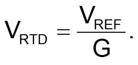
Using a 16-bit DAC and a 2.5-V reference to generate VREF, this RTD emulator can produce 0 to 830 mV in 12.7-μV increments. This easily covers the RTD temperature range of –200 °C to 384 °C, according to the sensor datasheet from Omega Engineering Corp. [1]. By changing the gain of the differential amplifier or the range of VREF, you can easily adjust circuit parameters for different ranges.
Also in this circuit, the RTD voltage is independent of the current source. You can use a 100-μA or 1-mA current source, or even a resistor, to provide the required current and still get the same RTD voltage for all three cases. The RTD voltage is independent of the value of the load resistor as well.
To emulate nonlinear characteristics of a real RTD, use a lookup table to generate voltages according to discrete temperature values, all under software control. The same circuit can be used with minimal modifications to emulate thermistor characteristics. Doing this requires a new lookup table to allow the software to generate voltages matching the temperature/voltage curve of a chosen thermistor.
Reference
- “RTD Temperature vs. Resistance Table,” www.omega.com/temperature/Z/pdf/z252-254.pdf