When a system's specifications call for a lowpass filter with a steep frequency-cutoff characteristic, an engineer can opt for a “brick-wall”- filter design that features a sharp transition band. For example, in an FM stereophonic-broadcast system, the lowpass filter in the baseband audio's left and right channels should have a –3-dB cutoff frequency of at least 15 kHz, a passband ripple of less than 0.3 dB, a stopband start frequency of at least 19 kHz, a stopband attenuation greater than 50 dB, and identical phase response for both channels.
The filter should provide adjustable gain to maximize SNR at the audio processor's first stage. The filter's frequency response should also include a notch at 19 kHz to achieve maximum attenuation at the FM-subcarrier pilot-tone frequency and thus minimize phasing problems. To reduce manufacturing costs, the filter should require no in-process adjustments. Conventional analog active-filter designs cannot meet these goals at reasonable cost and complexity without time-consuming adjustments. This Design Idea outlines an active-filter-synthesis approach that reduces a filter's sensitivity to passive-component tolerances and enables construction of inexpensive, high-order and highly selective filters.
 |
|
| Figure 1. | This seventh-order, elliptic, lowpass, passive-filter prototype features a 15-kHz cutoff frequency and stopband rejection exceeding 50 dB. |
The design process begins with selection of an appropriate passive-filter topology – in this example, a seventh-order elliptic filter with 50 Ω input and output impedances (Figure 1). Setting the beginning of the stopband frequency span at 18.72 kHz produces a notch at the 19-kHz stereo-pilot frequency. Using the following equation to transform each component's impedance leaves the filter's amplitude-versus-frequency response characteristics unaltered.
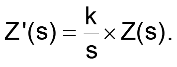
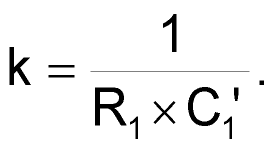
As a result of the transformation, all resistors undergo transformation into capacitors, and adjusting the value of parameter k yields reasonable capacitance values for using 10%-tolerance parts. In this instance, select a value of 2.2 nF for C1ʹ:
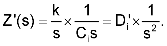
Inductors transform into resistors, and using 2%-tolerance or better components meets the circuit's requirements. Capacitors transform into “supercapacitors” whose impedance exhibits a 1/s2 dependence:
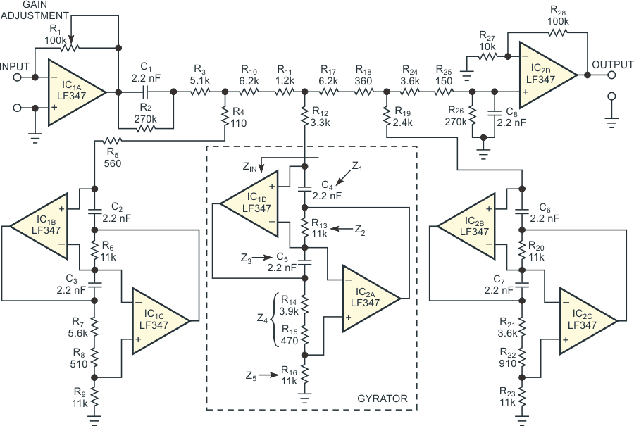
Selecting a topology for a passive filter that contains the maximum number of inductors and references all capacitors to ground yields a transformed filter that consists of many resistors, several supercapacitors, and only two capacitors. You cannot obtain a supercapacitor as an off-the-shelf component, but its electrical analog comprises a few operational amplifiers and resistors (Figure 2). The following equation defines the gyrator's input impedance, ZIN, with respect to ground:
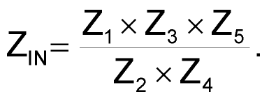
Selecting Z1 = Z3 = 1/Cs in the equation, setting capacitor value C at 2.2 nF, replacing impedances Z2 and Z5 with R = 11 kΩ, and setting Z4 = R4 yield a solution for Diʹ:
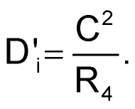
Figure 2 shows the filter's final schematic. Potentiometer R1 adjusts the overall gain, and connecting resistors R2 and R26 in parallel with capacitors C1 and C8 prevents dc blocking. The finished filter design uses medium-tolerance resistors, only eight capacitors, and two LF347 quad operational amplifiers – few amplifiers for a seventh-order active filter that requires no component adjustments to meet its specifications. Thanks to the design's precise implementation of the pilot-tone-rejection notch, the filter's measured attenuation at 19 kHz exceeds 60 dB.
 |
|
| Figure 2. | The finished circuit design eliminates inductors and substitutes gyrators as “supercapacitors.” Using medium-tolerance components and quad op amps to reduce component count minimizes circuit cost. |