I recently published a Design Idea (DI) showing some very simple circuits for PWM programming of standard regulator chips, both linear and switching, “Revisited: Three discretes suffice to interface PWM to switching regulators” (Ref. 1)
 |
|
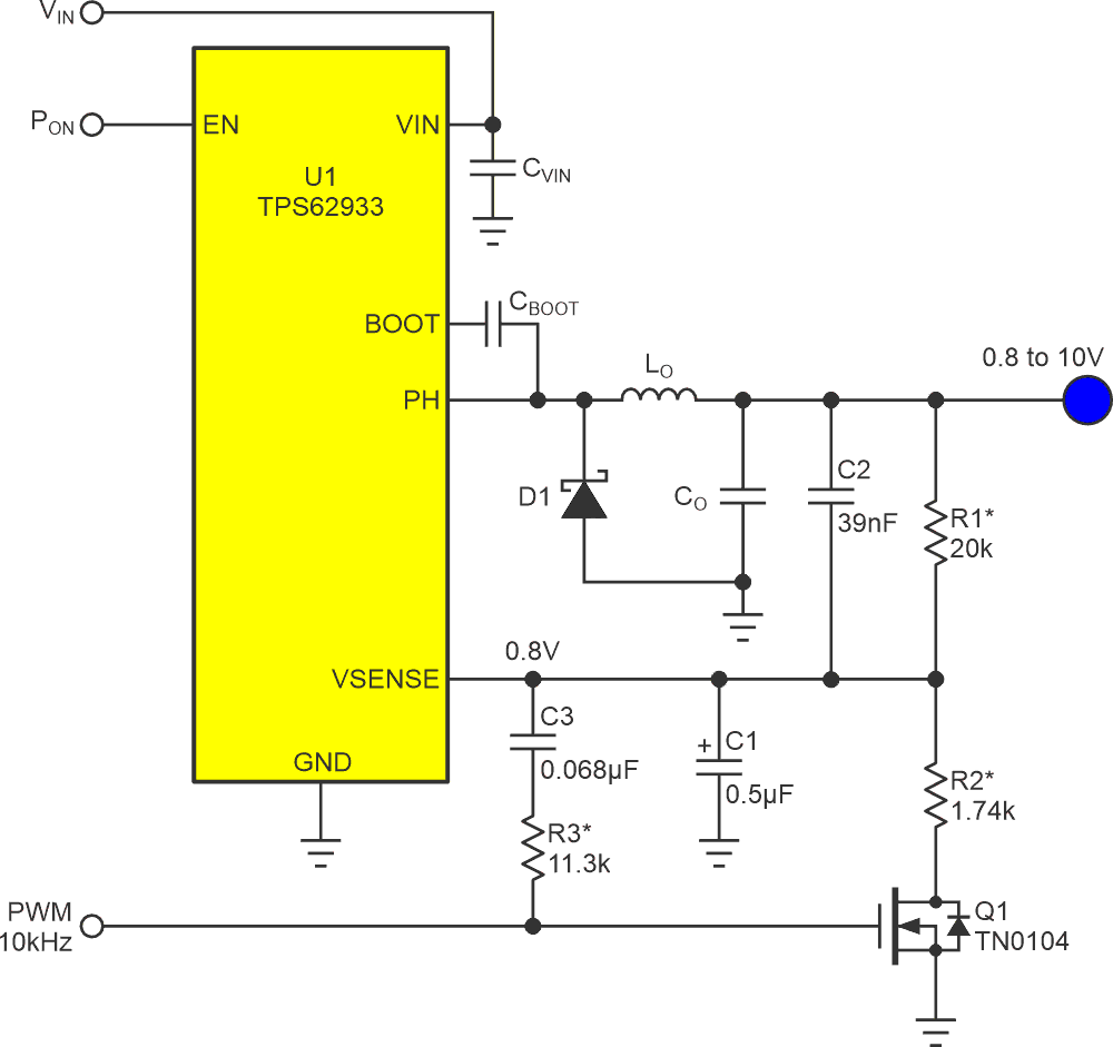
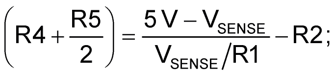
| Figure 1. | Five discrete parts comprise a circuit for linear regulator programming with PWM. |
Figure 1 shows one of the topologies “Revisited” visited, where:
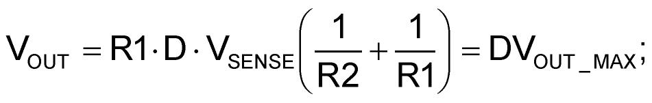
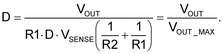
R1 = recommended value from U1 datasheet;
D = PWM duty factor = 0 to 1;
For parts shown
An inherent limitation of the Figure 1 circuit is its inability to program VOUT < VSENSE. Its minimum VOUT = VSENSE @ D = 0.
 |
|
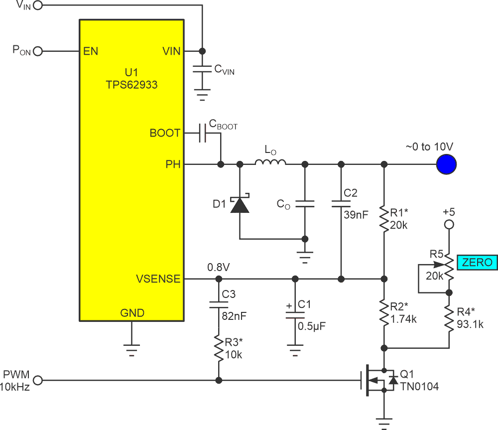
| Figure 2. | In order to make VOUT programmable down to zero volts, add R4 and (optionally) R5 trimmer. |
For most applications this doesn’t amount to much, if any, of a problem. But sometimes it would be useful, or at least convenient, for VOUT to be zero (or thereabout) when D = zero. Figure 2 shows an easy modification that can make that happen, where:
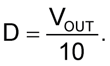
R1 and R2 chosen as in Figure 1;
For part values shown
A cool feature of the Figure 1 topology is that, unlike some other schemes for digital power supply control, only the precision of R1, R2, and the regulator’s own internal voltage reference determines regulation accuracy. Precision is wholly independent of external voltage references. It remains equal to the precision of R1, R2, and VSENSE (e.g., ±1%) for all output voltages.
Unfortunately, as the ancient maxim says, something’s (usually) lost when something’s gained. In gaining VOUT < VSENSE capability, the Figure 2 circuit loses that feature, and for outputs less than full scale, VOUT precision becomes somewhat dependent on the +5v rail. This is where the R5 trimmer comes in handy.
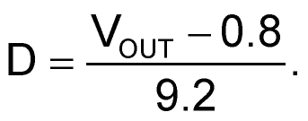
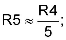
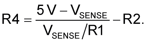
The design equation
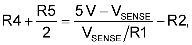
makes the values chosen for the R4, R5 pair dependent on the accuracy of the 5v rail. They can only be as correct as it is. This makes output voltages somewhat suspect, especially when they approach zero. Including R5 and adjusting it for VOUT = 0 @ D = 0 makes low VOUT settings accurately programmable. If that isn’t a critical factor, then R5 can be omitted, just make
The simplicity of the arithmetic for computing D from the desired VOUT is also a desirable feature of Figure 2.
In closing: This DI revises an earlier submission: “Three discretes suffice to interface PWM to switching regulators” (Ref. 2).
References
- Woodward, Stephen. “Revisited: Three discretes suffice to interface PWM to switching regulators.”
- Woodward, Stephen. “Three discretes suffice to interface PWM to switching regulators.”