It’s just a fact, I’m curiously fond of topologies that combine PWM switching and filtering circuitry with power handling devices like adjustable voltage regulator chips. This scheme makes power-capable DACs with double-digit wattage outputs. For example, “0 V to -10 V, 1.5 A LM337 PWM power DAC” (Ref. 1).
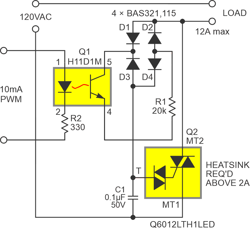
The simple circuit in Figure 1 joins this favored family but makes its siblings look weak and wimpy by upping the power ante by more than a factor of 10. It attains output capabilities over a kilowatt and gets there with a total parts count of only nine inexpensive discretes. Here’s how it works.
 |
|
| Figure 1. | The quadrac Q2 conduction-angle triggering time constant = R1C1/D, where D is the PWM duty factor from 0 to 100%. |
The power control method in play is variable AC phase angle conduction via a quadrac (also sometimes called an alternistor). Quadracs are bidirectional thyristors that comprise the dual functions of a triac (to do the power switching) and an integrated diac (to trigger the triac).
They’re popular in applications like variable-speed power tools and lamp dimmers because they’re cheap, efficient, and durable. What’s also nice is that the only support components they need for AC power control are a small potentiometer and a timing capacitor (both also cheap) to adjust triggering delay and thereby the phase angle of conduction, thence power output Q2 is wired in exactly that traditional way, except that opto-isolator Q1 and R1 fill the role of the pot. The duty factor (D) of Q1’s PWM input sets its average conductance and thereby the effective trigger delay from a D = 1 minimum of ~1.7 ms for an upper 95% output power, down to a D = 0 delay that’s longer than the entire 8.33 ms AC half-cycle. Which is to say: OFF. The PWM cycle rate isn’t critical but should be at least 10 kHz to avoid possible annoying beat frequencies since it’s not synchronized with the 60 Hz AC cycle.
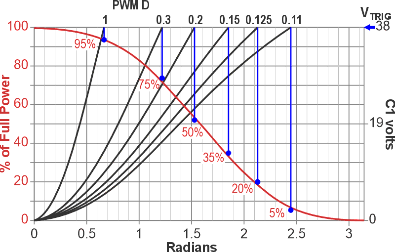
The relationship between D, phase angle, and percent power output is equal to the time integral of
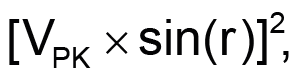
which is shown in Figure 2.
 |
|
| Figure 2. | The (VPK×sin(r))2 power output versus the PWM D. The right axis is the voltage of the trigger capacitor (C1), the left axis is the fraction of the full output power versus trigger phase, and the x-axis is the AC phase in radians. |
Because Q1, unlike Q2, isn’t bidirectional, the D1-4 diode bridge is necessary to keep it upright despite 60-Hz phase reversals. Q1’s typical current transfer ratio of 80% makes ~10 mA of PWM drive current necessary. Current limiter R2’s 330 Ω assumes a 5-V rail and a low impedance driver and will need adjustment if either assumption is violated. The VC1 trigger voltage is 38 V ±5 V with ±3 V max asymmetry. These tolerances place a limit on D versus power precision.
The full throttle Q2 power output efficiency is around 99%, but Q2’s max junction temperature rating is only 110 °C. Adequate heatsinking of Q2 will therefore be wise if outputs greater than 200 W and/or toasty ambient temperatures are expected.
Reference
- Woodward, Stephen. "0 V to -10 V, 1.5 A LM337 PWM power DAC."