Accurate, inexpensive, and mature platinum resistance temperature detectors (PRTDs) with an operating range extending from the cryogenic to the incendiary are a gold (no! platinum!) standard for temperature measurement.
Similarly, the 4 to 20 mA analog current loop is a legacy, but still popular, noise- and wiring-resistance-tolerant interconnection method with good built-in fault detection and transmitter “phantom-power” features.
Figure 1 combines them in a simple, cheap, and cheerful temperature sensor using just eight off-the-shelf (OTS) parts, counting the PRTD.
 |
|
| Figure 1. | PRTD current loop sensor with IX = 500 µA constant current excitation. |
In this figure

PRTD resistance

R1 and R2 are 0.1% tolerance (ideally).
Here’s how it works.
The key to measurement accuracy is the 2.50-V LM4040x25 shunt reference, available with accuracy grade suffixes of 0.1% (x = A), 0.2% (B), 0.5% (C), and 1% (D). The “B” grade is consistent (just barely) with a temperature measurement accuracy of ±0.5 °C.
R1 and R2 should have similar precision.
R2 throttles the 2.5 V to provide T1 excitation current

Because A1 continuously servos the IO output current to hold pin3 = pin4 = LM4040 anode, the 2.5 V across R2 is held constant, therefore IX is likewise.
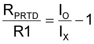
Thus, the voltage across output sense resistor R1 is forced to VR1 = IX(RPRTD) and

This makes

and

for

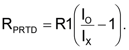
Wrapping it all up with a bow:

Note that accommodation of different RPRTD resistance (and therefore temperature) ranges is a simple matter of choosing different R1 and/or R2 values.
Conversion of the IO reading to RPRTD is an easy chore in software, and the step from there to temperature isn’t much worse, thanks to Callendar Van Dusen math (Ref. 1).