Converting frequency signals to loop current signals creates an economical result for process industry applications.
Process industry applications commonly employ multiple motors. Their speeds are monitored by tachometers using magnetic pickups from gear wheels mounted on the motors’ shafts. The tachometers produce pulses whose frequencies are proportional to their speeds. Local displays of speeds is generally done by counter/timer-based LEDs or LCDs.
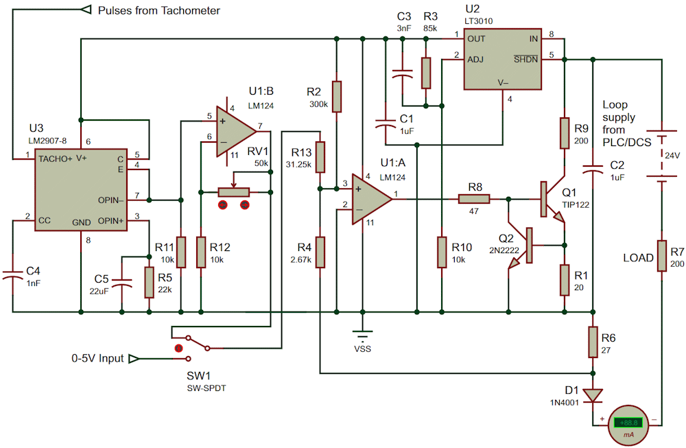
Special modules incorporating expensive counter/timers find use for recording these speeds in control room-based programmable logic controllers (PLCs) and more complex distributed control systems (DCSs). Shielded cables are necessary to carry these pulse signals to the control room, as the signals may induce noise in adjoining cables carrying conventional analog signals. Such an approach is expensive. A more economical alternative solution would be to convert each frequency signal to a 4-20 mA loop current signal and then transport it to the control room using less expensive cables like those carrying analog signals. Figure 1’s circuit does exactly this.
 |
|
| Figure 1. | In one switch SW1 position, this circuit converts 0-5 kHz frequency signals to 4-20 mA loop current alternatives. In the other switch position, the circuit converts 0-5 V into 4-20 mA loop current. |
The frequency to voltage conversion circuit discussed here is based on an industry-standard LM2907 IC. This chip is extensively used in automotive applications and hence is easily available and inexpensive. It needs only three components to set the basic relationship between frequency and voltage. It uses a charge pump circuit to convert frequency to voltage.
- V output = VCC×F×R×C (In Figure 1’s circuit, R = R5, C = C4). F is pulse frequency.
- U2 is wired to give a 12 V output, which is fed to the circuit.
- With VCC as 12 V and substituting the component values shown in the circuit, the voltage output works out to 0.264 V/kHz.
Exact values for R5 and C4 are not necessary; approximate values are sufficient. The signal is amplified by U1B so that a voltage relationship of 1 V/kHz is obtained by tuning potentiometer RV1. C5 filters ripples; increasing its value filters ripples more effectively but also increases the response time. The portion of the circuit surrounding U3 converts 0 to 5 kHz into 0 to 5 volts.
The remaining portion of the circuit converts 0/5 V into 4/20 mA loop current. R2 determines the “zero” current of 4 mA. If an exact-value resistor is not available, R2 may be replaced with a potentiometer. R13 determines the current span value. Again, if an exact-value resistor is not available, it can be replaced with a potentiometer.
The current going through R2 plus the current going through R13 must be equal to current through R4, as these currents are at the + input of operational amplifier U1A, whose -ve input is grounded. A detailed description of a loop current converter with governing equations can be found in my earlier Design Idea “A 0-20 mA source current to 4-20 mA loop current converter” (Ref. 1).
As a bonus, this circuit converts 0-5 V into 4-20 mA loop current by flipping switch SW1 to the alternative 0-5 V input position. Multiple industrial sensors and transmitters generate 0-5 V outputs for the parameters they monitor. This circuit may be used to comfortably connect such sensors and transmitters to PLCs and DCSs. Linearity and accuracy are primarily dictated by the LM2907 IC. A simulation study of this circuit indicates accuracy of better than ±5%.
Reference
- Ramalingam, Jayapal. "A 0-20mA source current to 4-20mA loop current converter."