This basic beat oscillator makes continuous wave keyed code and single sideband suppressed carrier signals audible.
A recent Design Idea from contributor Gavin Watkins shows an inexpensive add-on beat frequency oscillator (BFO) [1] for inexpensive and vintage short-wave radio receivers. It makes reception of highly efficient amplitude modulation transmission formats like CW (continuous wave keyed code) and SSB SC (single sideband suppressed carrier) possible on basic, inexpensive radios that otherwise couldn’t. It’s very cute and
thrifty.
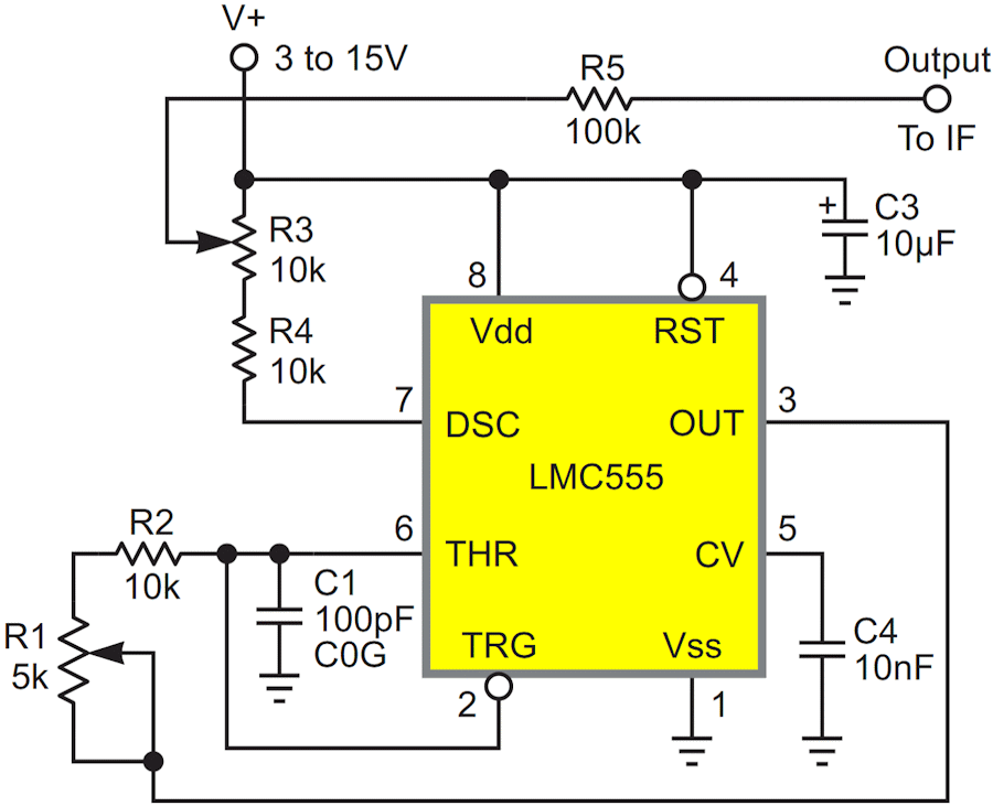
Today’s Design Idea (Figure 1) does a similar job, but takes less space while needing only about half as many components. Also, the parts it does require are easier to source.
 |
|
| Figure 1. | This 455 kHz intermediate frequency beat frequency oscillator is tuned by R1. The amplitude of the injected IF signal is adjusted by R3. It works happily with a wide range of supply voltages and so needs no regulator. |
Here’s how it works.
Both single-sideband suppressed carrier (SSB SC) and (the somewhat misleadingly named) keyed continuous wave (CW) radio transmissions share the lack of a steady carrier wave reference. Eliminating the carrier and redundant sideband is good because it increases transmission efficiency in both bandwidth and transmitter power utilization. But it adds complexity to the receiver because then it must provide the missing reference frequency to produce an audible and intelligible signal.
Some basic, mainly older, receivers can’t do that. What to do for them? We can simply tack on a BFO. An add-on BFO works by injecting a low-level signal into the receiver’s IF chain that:
- Is manually adjustable to be the correct amplitude that allows the receiver’s existing automatic gain control (AGC) loop to respond to and follow the incoming RF signal normally.
- Is tuneable to accurately match and sum with the IF frequency so that, when mixed with the IF signal by the receiver’s final detector, it can recreate the SSB suppressed carrier and modulation audio.
The oscillation frequency is given by the following equation:

where
CS = stray capacitance = ~15 pF
TD = internal 555 delay (See [2]) = ~212 ns
With the component values shown, it’s tunable over 455 kHz ±20%.
The oscillator output is taken from pin 7 rather than 3 to maximize isolation and minimize coupling between the IF chain and BFO oscillation frequency. This is important for audio quality.
The output amplitude is adjusted by R3 over a range of 0 to (V+)/2.
Reference
- Watkins, Gavin. "Add-on beat frequency oscillator (BFO) for shortwave radio."
- Woodward, Stephen. "Improve 555 frequency linearity."