Abstract
Measuring the signals from extremely high impedance sensors is a difficult task. These sensors can have output impedances in the Teraohms (1×10¹² Ω). The tiny signal currents coming from sensors such as Faraday cups and photodiodes require electrometer-grade amplifiers for measurement. These amplifiers can resolve currents as small as 1 femtoampere (1×10–15 A) when configured as a transimpedance amplifier (TIA). Many applications require protecting these circuits from overrange. The protection components are expensive and degrade the circuit performance. This article explains these protection circuits along with methods for improving performance while lowering costs.
The Need for Protection
High impedance current output sensors are designed to operate with zero voltage bias. The TIA circuit forces the voltage across the sensor to 0 V. Zero sensor voltage is possible when all of the sensor current flows through the feedback resistor. Negative feedback forces the amplifier output to the voltage that causes the necessary current to flow in the feedback resistor. The required output voltage is equal to the sensor current multiplied by the feedback resistance per Ohm’s law.
The output voltage swing of the amplifier limits the maximum current through the feedback resistor. The sensor voltage cannot be held at zero when the sensor current is greater than the maximum feedback resistor current. The excess current increases the sensor voltage until an alternate path can sink it. The electrostatic discharge (ESD) protection devices in the amplifier typically sink this excess current.
Many applications cannot tolerate this kind of overrange because it can have a long recovery time and it can interfere with other channels. Long recovery times are due to the capacitance, which must be discharged. All of the sensor, cabling, and input capacitance must be discharged through the feedback resistor. The feedback resistor limits the rate of discharge. Worse still, the dielectric absorption of these insulators creates residual currents in response to the voltage change. These residual currents can take minutes or hours to fully dissipate. Interference is another problem in systems with multiple sensors in close proximity to each other. The voltage change on the overloaded sensor capacitively couples to the adjacent channels. This coupling capacitance injects current and corrupts the measurements of the adjacent channels.
Limiter Circuits
A feedback limiter circuit is needed to avoid the overrange problems. Feedback limiters include a nonlinear feedback element that can handle large amounts of current without high voltages that clip the amplifier output. A simple feedback limiter circuit adds a diode in parallel with the feedback resistor (Figure 1). As the output voltage decreases, the diode (D1) starts to conduct some current from the sensor. The diode’s exponential characteristic allows it to handle very large amounts of sensor current without clipping the amplifier’s output.
 |
||
| Figure 1. | TIA with diode limiter. | |
The diode used for the limiter must be selected properly to avoid ruining the circuit performance; this is a challenging task for very high impedance TIA circuits. At low output voltages the diode behaves as a resistor whose resistance depends on the saturation current (IS). This resistance is typically called the diode shunt resistance. The shunt resistance is in parallel with the feedback resistor, so it must be much larger than the feedback resistor to avoid corrupting the transfer function of the TIA. This is difficult because the shunt resistance has an exponential temperature dependence; its value falls by half for every 10 °C increase in temperature. The enormous feedback resistances used in electrometer circuits require careful diode selection. These components require specially designed low leakage diodes or the gate diode of a small discrete JFET. These specialty diodes are usually quite expensive, costing a few dollars each.
The exponential current voltage characteristic of the diode is also the cause of a serious limitation of this circuit. Once the applied voltage (VA) becomes greater than the thermal voltage (kT/q), the exponential characteristic starts to dominate. The linearity of the simple limiter TIA circuit begins to degrade once the output voltage magnitude is greater than the thermal voltage. The thermal voltage is only 26 mV at room temperature, which limits the dynamic range of the circuit considerably.
It is possible to reduce the output range limitations of the simple limiter using guarding techniques (Figure 2). The voltage across the limiter diode (D1) is driven to zero with the R1 resistor. This voltage (VGUARD) can be pulled down by the amplifier through the output diode (D2). Feedback limiting starts once VGUARD exceeds the thermal voltage, allowing D1 to conduct. Resistor R1 can be sized to require a considerable amount of current from D2 to create this voltage drop. For example, a 1 kΩ resistor requires 26 µA of diode current to cause a 26 mV drop; this is considerably more than the tens of femtoamperes required by a simple limiter. These large currents ease the requirements of the output diode. Conventional diodes may be used for D2 instead of the specialty diodes required for D1. This circuit allows for adjusting the output range by replacing D2 with a series string of diodes or a single Zener diode. These circuits may also be modified for bidirectional limiting by replacing each diode with the appropriate anti-parallel diodes or back-to-back Zener diodes.
 |
||
| Figure 2. | TIA with guarded diode limiter. | |
The guarded circuit offers considerable performance improvement compared to the simple diode limiter, but it still depends on the performance of the expensive D1 diode. These price and performance limitations can be eliminated by using an electrometer amplifier that has an internal guard buffer with guard pins. One such amplifier is the ADA4530-1. The internal guard buffer of this amplifier drives the ESD protection diodes with a guard voltage. This guard voltage keeps the input bias current low by eliminating voltage drops across the ESD diodes. These ESD diodes are specially designed to have very low leakage currents.
These on-chip ESD diodes can be used in the guarded limiter circuit (Figure 3). The ESD diodes now serve the function of specialty diode D1. The guard buffer has a 1 kΩ output resistance that functions as resistor R1. The only external component is the output diode, D2. This output diode is connected between the guard pin (Pin 7) and the output voltage. The circuit starts to limit once a thermal voltage is created onto the VGUARD node.
 |
||
| Figure 3. | TIA guarded ESD diode limiter. | |
Measurement Results
 |
||
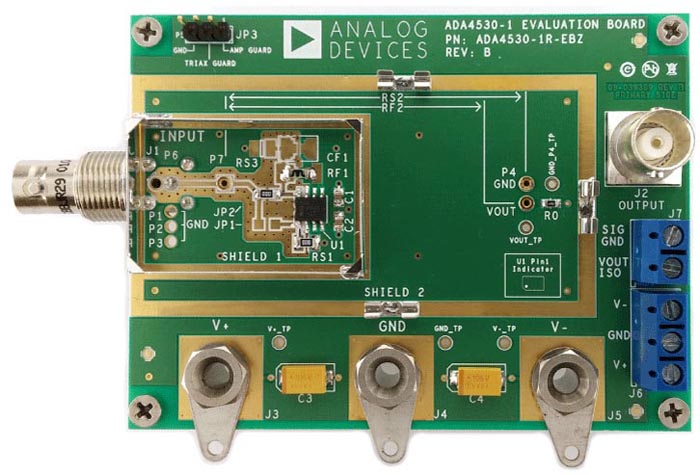
| Figure 4. | ADA4530-1R-EBZ-TIA Evaluation Board. | |
A 100 GΩ TIA circuit was constructed to compare the performance of the simple diode limiter using a specialty low leakage diode to the guarded limiter using ESD diodes. The part numbers of all of the components used are found in Table 1. The electrometer amplifier evaluation board was modified to construct these circuits (Figure 4). It is important to mention that the amplifier guard output should not be used to drive the guard rings because its voltage changes. Guard rings should be driven with the signal ground connection taken from the noninverting amplifier input.
| Table 1. | Test Circuit Components | ||||||||||||||||||||||||
|
|||||||||||||||||||||||||
The circuits were evaluated by forcing a test current from an electrometer-grade source measure unit (SMU) (Keithley 6430) into the circuit and measuring the output voltage with a high accuracy DMM (Keysight 3458a). All testing was done at 25 °C with ±5 V power supplies. The test current ranges from 10 fA to 100 pA and the output voltage ranges from 1 mV to 5 V (Figure 5). The linearity is evaluated by plotting the difference between the ideal output voltage and the actual output voltage (Figure 6). The baseline performance is established without any feedback limiter (black curves). Without limiting, the error is less than 1 mV until the amplifier output swings to the power supply rail.
 |
||
| Figure 5. | TIA transfer function for measured limiters. | |
The simple diode limiter circuit was implemented using the low leakage PAD1 diode. The PAD1 diode is a common choice for this kind of application. The performance of the simple limiter (red curves) is identical to the baseline at low test currents. This means that the saturation current resistance of the diode is significantly higher than 100 GΩ (at 25 °C). As expected, the output range is quite limited; the output error exceeds 1 mV at 600 fA of test current. This test current level corresponds to a 60 mV output voltage range.
 |
||
| Figure 6. | TIA transfer function error for measured limiters. | |
The guarded ESD diode limiter (Figure 3) was evaluated with a low cost 1N4148 output diode (D2). Once again, this guarded limiter performance (blue curves) matches the baseline performance at low test currents. The low leakage ESD diodes integrated on the electrometer amplifier are responsible for this good performance. The 1N4148 simply provides the feedback current. The dynamic range is improved, too, requiring 2.5 pA of test current before the error exceeds 1 mV. This corresponds to a 250 mV output range, which is a 4× improvement.
The flexibility of this circuit was demonstrated by replacing the output diode with a 1N5230 Zener diode. At low test currents, this circuit performs identically to the baseline circuit (green curves). The dynamic range is extended beyond the standard diode. 10 pA of test current is required before the error exceeds 1 mV. This represents a 1 V output range. This circuit begins to limit with Zener currents much less than the specified 1 mA to achieve the 4.7 V nominal breakdown voltage. It is desirable to operate the Zener diode at its rated breakdown for the largest dynamic range with reduced temperature sensitivity. Lower current Zener diodes are available, such as 1N4624. The operating current may also be increased by adding an external resistor between VGUARD and signal ground. A 27 Ω resistor will require 1 mA of Zener current to drop a thermal voltage across the ESD diodes.
In conclusion, electrometer-grade sensor interfaces often require feedback limiting circuits. These circuits require specialty diodes that cost several dollars each. These specialty diodes can be replaced by the ESD diodes of an electrometer amplifier with a guard buffer output such as the ADA4530-1. This approach creates a high performance limiter that only requires a single external component that costs pennies a piece.