A solar-powered lead-acid battery charger can ensure that the battery remains fully charged over a wide temperature range. The ideal charging circuit compensates for temperature and sunlight variations, including recovery from shading.

Solar or photovoltaic panels comprise multiple solar cells that connect in series. An ideal solar cell appears as a current source that connects in parallel with a rectifying diode. The photovoltaic current, IPH, depends on the sunlight falling on the solar cell. In the dark, a solar cell is simply a diode. A solar cell residing in shade has limited current-generating and -carrying capability, resulting in limited current-carrying ability for the entire solar panel. The current-output ability of a solar cell falls with a reduction in sunlight (Figure 1).
 |
|
| Figure 1. | A solar cell’s current output decreases with a reduction in sunlight. |
Figure 2 shows the effect of temperature on a solar cell’s output voltage; that is, solar-cell output voltage decreases with an increase in temperature. This design uses a solar panel comprising a series of solar cells to charge a lead-acid battery when the solar panel is operating at the maximum power point. A number of design steps are necessary to ensure that the cell operates continuously at the “knee” of the IV curve, thus providing maximum power to the load (figures 1 and 2).
 |
|
| Figure 2. | A solar cell’s output voltage decreases with an increase in temperature. |
The design in Figure 3 uses an 18-cell, 3 W SunWize Technologies SC3-6V solar panel as the input source. The design comprises one stage that monitors the solar-panel voltages using a SEPIC (single-ended-primary- inductor-converter) topology that employs a LM5001 controller. The LM5001 provides the output voltage that tracks the solar panel’s output voltage over the temperature range. A simple, cost-effective thermal-monitor circuit using a string of BAT54 diodes tracks the solar panel’s voltage over a temperature range of 25 to 100 °C.
 |
|
| Figure 3. | The solar charger system uses an 18-cell, 3 W solar panel as the input source. The system comprises two stages, in which the first stage monitors the solar panel’s voltages using a SEPIC topology and provides the output voltage, which tracks the input of the solar panel’s voltage over the temperature range. |
The second stage of the design takes the output of the first stage and boosts the input voltage to a nominal 13.3 V at 25 °C and 14.4 V at 100 °C. The second stage is configured as a constant-current controller to charge the 12 V lead-acid battery that matches the optimum charge technique for a lead-acid battery.
The charging current into the battery also varies to ensure that the solar panel does not exceed its maximum power at high temperatures. You accomplish this task by reducing the input current to the battery at higher temperatures. Again, a cost-effective thermal-monitor circuit using BAT54 diodes provides feedback to adjust the output voltage and output current over the temperature range.
The design incorporates recovery from shading, overvoltage protection, dual-stage current regulation, and operation over a wide temperature range. Shading reduces the solar panel’s output current and can force the solar panel, which has limited output-power capability, into an overload condition to the right of the knee shown in Figure 1. A National Semiconductor LM4041 monitors the input voltage, and, if the input voltage decreases due to shading on the solar panel, the unit will undergo restart mode once you remove the shading-induced false condition.
Under full sunlight, the solar panel delivers 198 mA of current under loaded conditions at 25 °C (Table 1). A shaded solar panel’s current decreases to 30 mA, depending on the extent of the shading. This decrease forces the solar panel into an overload condition because the battery requires a higher current than the solar panel can deliver, and the solar panel’s output voltage decreases from approximately 11 V to less than 4 V. The design incorporates dual-stage current regulation to provide optimum current under various temperature conditions.
| Table 1. | Test data over the operating-temperature range | ||||||||||||||||||||||||||||||||||||||||||||||||||||||||||||||||||||||||||||||||||||||||
|
|||||||||||||||||||||||||||||||||||||||||||||||||||||||||||||||||||||||||||||||||||||||||
Stage 1 of the design uses a SEPIC topology to take the output of the solar panel, which varies from 9 V at 25 °C to 6 V at 100 °C, as the input to the SEPIC. The SEPIC design uses a LM5001 operating at 780 kHz. The solar panel has a negative- temperature coefficient of –2.2 mV/°C per cell. For a panel comprising 18 cells, that coefficient amounts to –39.6 mV/°C for an unloaded panel. This coefficient implies that the solar panel’s voltage varies by –40 mV/°C. That is, if you get 9 V at 25 °C, then a variation of 75 °C (40 mV/°C), or 3 V will occur at 100 °C.
A SEPIC is a dc/dc converter that allows the output voltage to be greater than, less than, or equal to the input voltage and provides an output voltage that is of the same polarity as the input voltage controlling the duty cycle of the control transistor (Figure 4).
In continuous mode – that is, when the input inductor current, IL1 – never falls to 0 A – the average voltage across VC1 equals the input voltage, provided that the value of C1 is large enough. You can easily visualize this operation because the average voltage across inductors L1 and L2 is 0 V; the loop comprising VIN, L1, C1, and L2 highlights the fact that VC1 equals the input voltage. Because C1 blocks dc current, the average current through capacitor C1 and IC1 is 0 A. Thus, the average current through L2 is the average load current and independent of input current.
 |
|
| Figure 4. | A SEPIC is a dc/dc topology that allows the output voltage to be greater than, less than, or equal to the input voltage. |
Replacing inductor L2 with a transformer yields an isolated version of a SEPIC. Using a coupled inductor – that is, a 1-to-1 transformer – in place of L1 and L2 makes the design more cost-effective and allows you to replace inductors L1 and L2 with one magnetic element. You can then redraw the schematic (Figure 5). Turning on Q1 holds the positive C1 terminal that connects to the drain of Q1 at ground level, and 1-to-1 transformer T1 induces a voltage equal to the input voltage at the junction of D1 and C1. Thus, the voltage across capacitor C1 equals the input voltage. The SEPIC can provide an output voltage that is greater than or less than the input voltage, according to the follow equation:
where VOUT is the output voltage, VIN is the input voltage, and D is the duty cycle of the main FET, Q1.
 |
|
| Figure 5. | Replacing the inductor L2 of Figure 4 yields an isolated SEPIC. |
Because the solar panel has limited current-output capability, you must consider the inrush-current capability of the circuit. The LM5001 control element operates at 780 kHz, which determines the internal soft start. The design incorporates an external soft-start circuit comprising D1/D1A, R, and soft-start capacitor, CSS, to extend the soft-start time and ensure that the solar panel does not become overloaded during turn-on (Figure 6).
 |
|
| Figure 6. | The design incorporates an external soft-start circuit to extend the soft-start time and ensure that the solar panel does not become overloaded during turn-on. |
By changing the value of RB in Figure 7 to adjust the voltage divider in the first stage of the SEPIC, you can adjust the SEPIC voltage’s setpoint to accommodate different solar-panel voltages. You can adjust a resistor divider comprising RT and RB to match the SEPIC’s reference voltage, typically 1.34 V at 25 °C, which the thermal board generates. A string of diodes generates a reference voltage that varies with temperature, thus providing temperature compensation to the design. The output of the first stage tracks the solar panel’s voltage and adjusts for varying temperature. It is critical that the reference circuit comprising the string of diodes be close to the hot spot to track the temperature variation.
 |
|
| Figure 7. | Changing the value of RB adjusts the SEPIC voltage’s setpoint to accommodate different solar panels’ voltages. You can adjust a resistor divider comprising RT and RB to match the SEPIC’s reference voltage, typically 1.34 V at 25 °C, which a thermal board generates. |
Battery-charge current
The second stage of the design comprises a SEPIC that operates in boost mode with constant current-charge control. This SEPIC charges the 12 V battery (Figure 8). Adjusting the value of RCA1 and RCA2 allows the adjustment of the battery-charging current to meet customer needs. You set the battery-charging current, IBAT, by dividing the reference voltage, which diode D1 – VD1’s forward drop sets; a typical value is 0.183 V at 25 °C. You then divide the result by RCA1 + RCA2. Because the reference voltage’s drop, due to D1, varies with temperature, this calculation accounts for the battery’s charging-current variation over temperature:
You set the two-stage current charging by bypassing the RCA2 current-set resistor once the temperature reaches 60 °C. Adjusting the RTB and RBB resistor values in Figure 8 sets the second-stage converter’s boost voltage.
 |
|
| Figure 8. | The second stage comprises a SEPIC that operates in boost mode with constant current-charge control and charges the 12 V battery. |
When the solar panel is in shade, its current capability decreases, resulting in overloading of the solar panel because of the fixed load on the solar panel; battery charging requires this fixed load. This overloading reduces the solar panel’s output voltage. The RBR/RTR divider that connects to the LM4041 in the first stage senses the solar panel’s output voltage, which initiates a restart mode by disabling the second stage of the circuit by pulling down on the enable pin of LM5001 (Figure 9).
 |
|
| Figure 9. | The RBR/RTR divider that connects to the LM4041 in the first stage senses the solar panel’s output voltage, which initiates a restart mode by disabling the second stage of the circuit by pulling down on the enable pin of LM5001. |
Once you remove the fault condition that shading causes, the solar panel’s voltage increases and allows the circuit to operate in the normal condition. The RBR/RTR divider senses when this voltage falls due to shading and rises again. The divider disables the second stage by pulling down the LM5001’s enable pin.
Boost overvoltage protection
If you accidentally disconnect the thermal board that houses both diode D1 in Figure 8 and diode string VREF in Figure 7, the boost output voltage will clamp to a fixed output voltage, thus preventing the output voltage from exceeding a fixed, predetermined level and preventing any damage to the battery.
The following equation determines the maximum boost voltage in case of an accidental disconnection of the thermal board:

where the LM5001’s reference voltage is nominally 1.26 V, ensuring that the battery does not exceed its overvoltage limit.
 |
|
| Figure 10. | The normal operating temperature for the charger is 60 °C. |
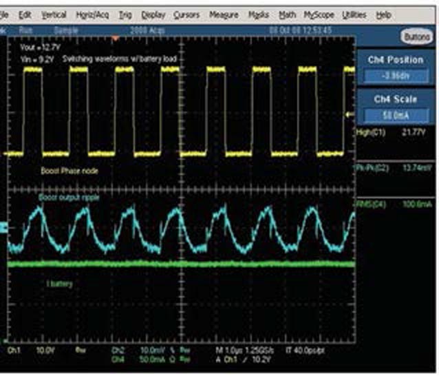
Test data on the unit over temperature in the lab using a dc source shows the performance of the two-stage solar-charger circuit. Figure 10 shows the battery-charging current versus temperature, and Figure 11 shows the voltage from the solar panel versus the overall charger efficiency. Figure 12 shows the typical waveforms of the circuit, highlighting the battery-charging current, the output ripple, and the switch node’s waveform.
 |
|
| Figure 11. | Efficiency falls off rapidly when the input voltage from the solar panel falls below 6.5 V. |
At 60 °C, the circuit moves into the second-stage current regulation, in which the current to the battery increases. The bolded text in column 7 in Table 1 highlights this transition point. This transition point provides optimum efficiency for the application because 60 °C is the normal operating temperature for the application.
 |
|
| Figure 12. | Typical converter waveforms highlight the battery load (top) and the boost output ripple current (bottom). |
The solar-powered lead-acid battery charger connects to the battery using an industry-standard onboard-diagnostic-connector interface or another equivalent connection mechanism. You can adjust the design to accommodate various solar panels with different power and voltage ratings. You can also modify this cost-effective design to incorporate short- circuit protection with only three extra components.Materials on the topic