Lightning is one of nature’s most intense and unpredictable forces, but thankfully, we have got technology to help us stay ahead of the storm. Lightning detectors are designed to pick up the electromagnetic signals generated by lightning strikes, giving users heads-up before a storm rolls in.
Looking to build a lightning detector module from scratch? This beginner’s guide for hobbyists and makers unlocks some of the practical secrets behind lightning detection in no time.
Let’s get started with a simple and doable approach: the AS3935 Franklin lightning sensor IC, a compact, low-power chip that lets even average electronics hobbyists add storm-sensing capabilities to their projects.
AS3935 can detect lightning strikes up to 40 km away, estimate their distance, and filter out false alarms caused by electrical noise. With support for both I2C and SPI interfaces and adjustable sensitivity for indoor or outdoor use, it’s pretty easy to integrate with popular platforms like Arduino or Raspberry Pi.
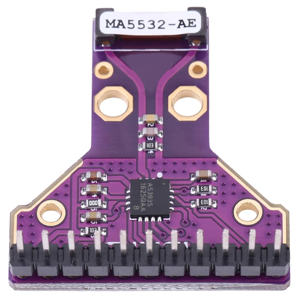
So, whether you are building a compact weather station or a smart outdoor gadget, AS3935 offers a reliable and engaging way to make your project climate aware. As far as I know, almost all ready-to-go lightning sensor modules available today (one of them can be seen in Figure 1) rely on the AS3935 Franklin lightning sensor from AMS, paired with Coilcraft’s 500-kHz to 2-MHz antenna, MA5532-AE.
 |
|
| Figure 1. | The module comprises AMS’s AS3935 lighting sensor chip and Coilcraft’s antenna. |
Almost a decade ago, I acquired the DFRobot version of the AS3935 module (SEN0290) and conducted some quick tests with my Arduino. The results were impressive, showcasing the system’s seamless functionality.
Figure 2 shows the elucidated schematic of a randomly picked AS3935 lightning sensor module (the original schematic has been simplified by removing unnecessary elements to improve clarity).
 |
|
| Figure 2. | The schematic diagram highlights design details of an AS3935 lightning sensor module. |
Sure enough, AS3935 boasts a tuned onboard antenna, a proprietary lightning detection algorithm, and distance estimation. However, its cost may be prohibitive for hobbyists and classroom projects. At the same time, the AS3935 chip might lack direct low-cost successors due to its niche application, technological advancements, and integration with other technologies.
So, what to do? Let’s take a look at some affordable analog circuit ideas (there is no reason at all for opining that the first one must be the best one).
Remember those crackling sounds on your AM radio during an electrical storm? Those were the static bursts of lightning strikes. Following that way, the block diagram in
Figure 3 depicts a simple setup for issuing audio-visual alerts about impending thunderstorms.
 |
|
| Figure 3. | Here is a simple setup for issuing audio-visual alerts about thunderstorms. |
The system uses an AM radio front-end to process signals from a tuned pickup coil. The output signals from the front-end – which comprises an RF amplifier, detector, and automatic gain control – are further amplified in the next stage, boosting the captured signals before they reach the pulse stretcher that drives the visual indicator. Adding to this, an audio oscillator segment’s tone bursts are used to drive a sounder, creating hearable alerts.
As a quick hint, consider using the venerable AM radio IC TA7642 for the front-end of your design. A classic for a reason: its reliability is unmatched.
Then again, if you are exploring wideband amplifier options, the MAR-1+ from Mini-Circuits’ MAR series is a great choice as it offers reliable performance across a broad frequency range (Figure 4).
 |
|
| Figure 4. | The monolithic amplifier offers reliable performance across a broad frequency range. |
As far as I am aware, both ICs mentioned above remain available, albeit through a limited number of suppliers. No surprise here – plenty of RF detector circuits can do the job brilliantly. After that, it’s all up to you.
Bear in mind that distant lightning, even when not seeable, can generate substantial electromagnetic interference (EMI). Whether it’s cloud-to-cloud or cloud-to-ground discharge, a lightning bolt carries an immense current that oscillates rapidly.
This arcing action produces a broad spectrum of harmonics, extending well into the high-frequency range of the radio spectrum. Thus, well-adapted versions of existing EMI/EMF detector circuits can be highly effective in capturing such electromagnetic transients caused by lightning discharges.
When it comes to detecting lightning today, we have got a solid lineup – RF detectors, electric field mills, and even optical monitors are all in play. They provide early warning of lightning hazards, and some systems can even trigger the start or stop of standby power generators remotely.
Let’s leave it here for the moment; present-day optical lightning detectors enhance early warning capabilities by identifying cloud-to-cloud discharges, which mostly precede cloud-to-ground lightning events. Figure 5 shows a canonical design idea to serve as a starting point for further experimentation and development. I have been using something that closely mirrors this approach to trigger my waterproof rooftop camera for capturing stunning lightning shots.
 |
|
| Figure 5. | The circuit generates a clean, fixed-duration output pulse in response to a rising edge input. |
This circuit employs a monostable configuration – typically using a 555 timer chip – to deliver a falling pulse approximately 1,000-ms long, based on the current RC component values. Rising edge detection is achieved by AC-coupling the phototransistor to the timer’s threshold input via a capacitor, ensuring that only transitions (not steady states) trigger the pulse.
The output (TP1) is suitable for driving optocouplers (normally-on or normally-off), enabling galvanic isolation for interfacing with downstream circuitry.
As has been noted, lightning produces an intense burst of light, making it detectable with a basic phototransistor in most scenarios. To enhance performance, the phototransistor can be paired with a suitable optical filter, providing a relatively uniform spectral response across the visible range and extending into the near-infrared region.
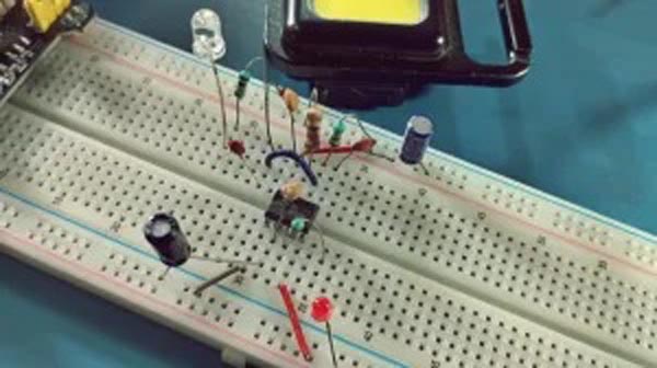
For preliminary testing, I set up a quick breadboard prototype and used a cheap keychain strobe light to simulate lightning flashes and evaluate the circuit’s response (Figure 6).
 |
|
| Figure 6. | The prototype used a cheap keychain strobe light to simulate lightning flashes. |
The choice of components was based on what I had readily available in the lab. I used the PT334-6C phototransistor, which was on hand, without exploring alternative options. Keep in mind that this is only a preliminary design. Significant effort is required to refine the optical front-end for optimal results.