Amplifying the human voice presents some tough challenges. One of the toughest of these is providing enough amplification to make sure a soft-spoken person can be heard while allowing sufficient headroom for people who speak loudly. If the amplification is too high, a loud voice or noise causes clipping of the audio waveform, which makes the output signal unintelligible and harsh to the ears.
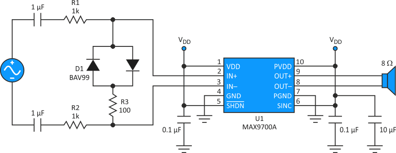
One solution to this dilemma is to limit the signal with a nonlinear transfer function, implemented by adding a few components to a standard application circuit (Fig. 1). When a positive or negative peak of the audio input exceeds the turn-on voltage of one of the back-to-back diodes (D1), the diode conducts and attenuates any further increase in the signal amplitude presented to the MAX9700A class D audio power amplifier. Resistors R1 and R2 add series impedance that prevents excessive loading of the audio source.
 |
|
| Figure 1. | A small-signal diode network prevents clipping by limiting an amplifier’s output voltage. |
During normal operation, the incoming audio signal sees little attenuation by the diode network, and the high input impedance of U1 prevents attenuation due to the higher source impedance. As input amplitudes increase, the transfer function shifts (Fig. 2).
 |
|
| Figure 2. | Signal attenuation by the simple diode network causes a nonlinear transfer of the higher-amplitude inputs. |
As you can see, the output tracks the input for low-level signals. Above input levels of about 0.5 V rms, there's a decrease in circuit gain. Gain compression is independent of the peak output voltage, as illustrated by the responses for various supply voltages. Note that the clamped 3.3- and 5-V inputs have the same response and are therefore superimposed. Also, the 2.5- and 3.3-V inputs show compression due to swing limits, even though no clamp is present.