As one of today's most interesting component families, high-value capacitors offer ratings ranging from tenths to tens of farads but suffer from relatively low working voltages. For example, Maxwell's PC10 ultracapacitor occupies an area about the size of a large postage stamp and the thickness of four stacked US 25-cent coins. The PC10 provides 10 F capacitance, a 2.5 A maximum discharge-current rating, and an 18 Ω ESR (equivalent-series resistance). However, its rated working voltage is only 2.5 V.
To accommodate a supply voltage greater than 2.5 V, you can connect two capacitors in series, halving the available capacitance and doubling the overall voltage rating. However, due to differences in leakage current and capacitance, the voltage at the capacitor's common connection can vary, and your design must ensure that you do not exceed either capacitor's maximum voltage rating. If the series-connected capacitors' charge and discharge currents are relatively small, you can connect equal-valued charge-balancing resistors across both capacitors. But for farad-range capacitors that can deliver amperes of current, you need a more efficient approach.
The theoretical voltage across a capacitor comprises its initial voltage, VC(0), plus the integral of the capacitance, C, multiplied by the capacitor's current over time:
In a two-capacitor divider, the current through both capacitors is identical, and the loop equation, including the supply voltage, becomes:
During charging to a 5 V-supply level, differences in tolerances between C1 and C2 or residual voltages on either capacitor cause the voltage across one capacitor's terminals to exceed 2.5 V and cause the other to fall below 2.5 V.
 |
|
| Figure 1. | This simple circuit requires only a single IC to balance the charges on two series-connected, low-voltage, high-value capacitors and maintain their common junction at one-half of the supply voltage. |
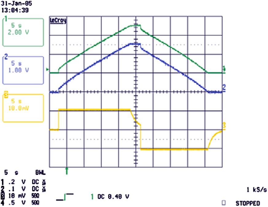
To overcome this undesirable mismatch, the LP2996 DDR termination regulator, IC1, sinks or sources current from both capacitors and actively maintains their voltages at one-half of the supply voltage (Figure 1). The LP2996 provides an active termination for DDR-SDRAM devices and can sink or source large amounts of current; its data sheet's nomenclature and labels reflect its intended memory-support role. The LP2996's Class B output, VTT, drives the capacitors' common connection, actively maintaining the junction at VDDQ/2 and becoming active only when the capacitors get out of balance. At balance, the LP2996 wastes no charging current and thus operates efficiently. The device's data sheet specifies that the LP2996's out-of-balance error amounts to a VTT offset of ±30 mV around the VDDQ/2 setpoint. Figure 2 shows charge and discharge waveforms for 1 A current steps.
 |
|
| Figure 2. | The oscilloscope waveforms within the active-balance circuit show the power-supply rail voltage (top trace), the midpoint voltage at the junction between the two capacitors (middle trace), and the charge/discharge current (lower trace, scaled to 1A per division). The traces reflect a 1 A charge interval to 5 V, followed by a 1 A discharge to 0 V. The waveform steps at the start of the charge and discharge intervals are due to the capacitor’s internal ESRs. |
This active balancing circuit does impose some limitations. Using a power supply rated at 5 V and 1 A, the two capacitors achieve charge balance in a maximum of 25 sec:
The initial charging interval overcomes any initial prebias charge on either C1 or C2. The steady-state current flow into and out of the LP2996 amounts to a fraction of the high current flowing through the capacitors and is just sufficient to overcome any tolerance mismatch in the two. The LP2996 includes thermal-shutdown protection, but an instantaneous short circuit across either capacitor may occur too quickly to activate the protection circuitry.
Thermal considerations determine the capacitor's maximum current-handling capability, and the PC10's data sheet derates the current downward from 2.5 A. You can connect 1 Ω current-limiting resistors in series with both capacitors if the power supply provides charging current in excess of 2 A.
Upon interruption of the power supplied to the circuit, the LP2996 imposes a self-discharge current of less than 1 mA, which represents a capacitor-"battery" discharge rate of 5000 sec per volt into an open circuit. You can reduce the LP2996's self-discharge current by applying an external control signal to its shutdown input. Upon power interruption, the two-capacitor string can supply a constant-current load of 1 A for 15 sec over a voltage change from 5 to 2 V. You can connect additional pairs of capacitors in parallel to provide additional current, but, depending on capacitance mismatches, initial bias voltages, and current demand, you may need additional LP2996s to maintain charge balance.