The voltage booster is a 'true' charge pump. When the output of the 555 is low, C4 charges from the supply via D1. When the output goes high, the positive end of C4 is forced high (to +24 V in a perfect world), and the charge is transferred to C5 via D2. This is a very common arrangement, and it's used in almost every high-side MOSFET gate driver ever produced. In those circuits, C4 is referred to as a bootstrap capacitor. The negative converter is a simple half-wave negative voltage doubler. Why is it a doubler? The RMS voltage feeding C4 is half the supply voltage (so 6 V with a 50:50 on/off ratio), and to get –12 V you use a voltage doubler.
It has become common to refer to this class of circuit as a charge-pump, regardless of its real modus operandi. There's no need to use the alternative names, as even though they are (IMO) more descriptive, the term 'charge-pump' is so common that it would not be sensible to try to change it. Likewise, it would be unwise to try to use either circuit for high current, as small switchmode modules can be obtained for very little cost if you happen to need more than 20 mA, or if you need reasonable voltage regulation.
The two circuits are shown with 100 μF caps, but these can be increased. The output cap (C5) is the most critical, as that determines the ripple on the output voltage. Using 100 μF, you can expect fairly low ripple with a 10 mA load. More than around 220 μF is unlikely to provide much benefit. Expect less than 1.5 mV (3 mV for the inverting circuit) with 100 μF. A larger cap also increases the average output voltage for a given load, which can be useful.
The 'minimum component count' version of the 555 astable multivibrator will change frequency slightly as the load is changed. Mostly this doesn't matter at all, and that's why I used it. The frequency is given by the formula
where R and C are the timing components
This isn't exact, and as noted it will change with the load. Ideally, the 'high' and 'low' periods would be identical, but as you can likely appreciate, this changes the operation very little. Simple circuits are (by definition) simple, and there's no point trying to make them perfect. Nothing built with a 555 timer is perfect – it's a general-purpose, utilitarian device. Yes, you can get fairly good accuracy from a 555, but mostly we really don't care very much. If we did want high accuracy, we'd use something else.
The alternative
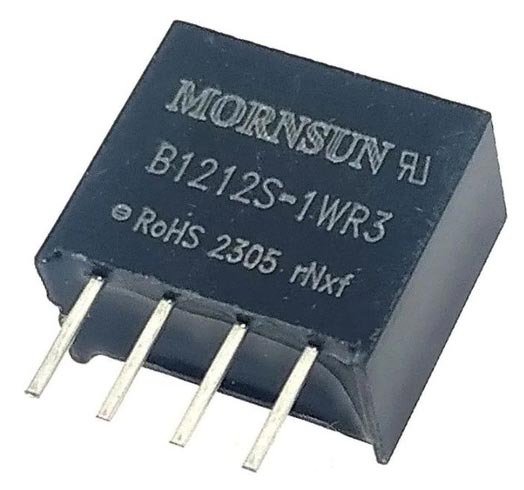
There is an alternative to a charge-pump, and there's every chance it will actually cost less than a 555 timer plus ancillary components. The one pictured in Figure 4 came from eBay, as I recall it was less than AU$4.00. They're available in a range of input and output voltages, so you can invert or boost almost any voltage you like. The one shown is rated for 1 W, so the 12 V version can provide 83 mA. They all manage to use the same pinouts, with Pin 1 as input ground, Pin 2 is input DC, Pin 3 is output negative and Pin 4 is output positive.
 |
|
| Figure 4. | Cheap (Chinese) 12 V-12 V DC/DC converter. |
Because they are isolated, the secondary can be at any voltage within the stated range in the datasheet. While most are tested to 1 kV, the voltage differential should normally be within the SELV (safety extra-low voltage) range, which is 42.4 V peak (30 V AC) or 60 V DC, although the definition varies from country to country. I wouldn't exceed ~150 V DC across the isolation barrier. Texas Instruments makes the UCC12050DVE, which is a single IC that includes an internal transformer (a similar IC is the UCC12051-Q1). It's limited to a maximum output of about 5 V at 100 mA. It requires a few external parts, but it's designed for 1.2 kV isolation (working value) and costs around AU$12.00 one-off. Few hobbyist applications will require this level of isolation, but it's apparent that the need exists for these devices (predictably, SMD only).
Similar modules are available from all major suppliers, with many costing less than AU$5.00 each. If you need to do something more adventurous you can experiment, but these small (12 × 10 × 6 mm) isolated DC-DC converters are often a far better proposition, and take up far less PCB real estate than a discrete solution. Being isolated means you have galvanic isolation (not for voltages over 150 V or so though), and the 1 W versions are capable of 83 mA (12 V). They are made for step-up, step down or direct conversion, and voltages of 5, 12, 15 and 24 V are common. Manufacturers include AimTec, CUI, Mornsun, Murata, Recom and Traco Power, plus innumerable Asian versions (often without a name printed on the case).
If you buy these from eBay, be careful. Some sellers want AU$15.00 or more for a module that should be less than AU$3.00, and in some cases the cost is greater than from the major suppliers. From these (e.g. Element14, Digikey, Mouser, RS etc.) you can expect to pay from AU$5.00 up to AU$15.00 or so, with no apparent difference between the modules regardless of the price. I find this puzzling, but it is what it is. The range of these just keeps getting better, and I expect that they'll be around for a long time, as they are so convenient. One down-side is noise, as they are not particularly quiet. A simple RC (resistor-capacitor) output filter will get rid of most of the noise though.
Note that some datasheets state that an input capacitor is required (between +VE and Ground) to minimise noise. Some also include a maximum capacitance that can be used in parallel with the output. Using more than the recommended maximum may cause startup problems.
Conclusions
These circuits are shown in their basic form only. While there's no doubt that a 555 based circuit will be perfectly alright in many cases, the little modules as shown in Fig 4 are a very hard act to follow. They are so simple to use that anything else doesn't really make sense.
I've suggested these modules in a number of other projects and I've used them in a number of designs. However, sometimes you just need to make something with what you have to hand, and 555 timer charge-pumps are ideal for low currents and where the voltage regulation just doesn't matter. Perhaps unexpectedly, this includes opamps that need a dual supply where only one supply is available. Most opamps don't care if the supply voltages aren't equal, and the only downside is that clipping will be asymmetrical. If the signal doesn't clip, there's no issue at all, other than the limited supply current.
Sometimes you just need a circuit that works, requires no parts you don't have in your component stash, and is easy (and cheap) to put together on a small piece of Veroboard. These circuits have been around for a long time, and while the 555 is not ideal, it does work and you can get them anywhere. A PCB for these charge-pumps will not be forthcoming, for the simple reason that there are so few parts it would be silly.