Convert a 4-20 mA signal to 0-20 mA and deliver it to a grounded load with no additional power supply needed.
Recently, EDN kindly published a design of mine for a micropower 4-20 to 0-20 mA current loop converter (Ref. 1). Shortly thereafter, in the grand tradition of the Design Idea circuit collaboration kitchen, also-frequent contributor Jayapal Ramalingam made a (challenging!) suggestion. He commented that the design might be more useful if, instead of needing an (albeit very small) local power supply, it was revised so as to need no local supply at all. It was a good point.
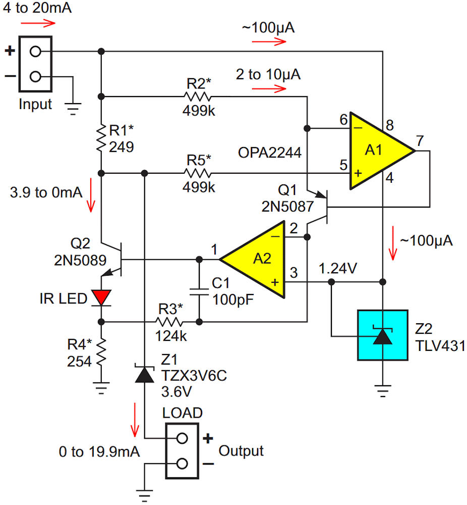
The challenging part, of course, was that this meant the converter would have to run solely from power stolen (more or less invisibly, hence “phantom”) from the same 4-20 mA signal it was working to convert. Sneaky. And tricky. I puzzled over JR’s intriguing suggestion until (eventually) a possible solution emerged from my muddled mental mist. Figure 1 shows the outcome of my foggy fancy: a “phantom power” converter:
 |
|
| Figure 1. | In this circuit, the 4-20 mA input current is converted to a 0-20 mA output while relying solely and exclusively on the input current for (phantom) power. Power-theft-related error is minimized by recycling the same 100 µA that runs the opamps to also bias precision voltage reference Z2. Asterisk’d resistors are 0.5% or better. |
Here’s how it works. Comparisons of Figure 1 to the circuit in the earlier design (Ref. 1) in Figure 2 reveal many obvious similarities, but a critical difference (other than no power supply in the “current” case) is how the precision shunt voltage reference is biased. In the prior circuit, since it runs from a constant local supply voltage, a simple resistor sufficed. But here, if we assume a 34 V range of acceptable loop supply, the 80 µA required by the TLV431 at 6 V could become 900 µA at 40 V, creating a cringe-worthy (and likely unacceptable) ~5% conversion error. Yikes!
![Schematic of a micropower current converter from [1].](https://www.rlocman.ru/i/Image/2026/07/25/Fig_2_Eng.gif) |
|
| Figure 2. | Schematic of a micropower current converter from [1]. |
Current recycling, however, improves accuracy of the conversion function to IOUT = 1.249(IIN – 4 mA) = 0 to 19.9 mA as IIN = 4 to 20 mA. The malingering 0.5% of full-scale error is the penalty paid for phantom power. After all, active devices, by definition, must be fed. And while 0.5% accuracy isn’t quite phantasmagorical, maybe it’ll do.
Other picky phantom phacts include the IR LED wired in series with Q2’s emitter. It’s not there to make light, which we couldn’t see anyway, but rather to use its 1 V minimum forward voltage to help accommodate A2’s ~200 mV minimum output that sits atop Z2’s 1.24 V. Likewise dictated by opamp limitations is the boost of R1 to 249 ohms and its minimum sensed voltage to 1 V. This accommodates the 2244’s common mode topping out at 900 mV below the positive rail.
In conclusion, thanks JR!
Reference
- Woodward, Stephen. "4-20mA to 0-20mA converter sips mere microamps."