This circuit enables you to generate remote control PWM test signals with a (very) generic (and cheap) chip.
A recent Design Idea (Ref. 1) illustrated the application of an interesting chip (the LTC6992) to remote control (RC) PWM test signal generation. Being familiar with neither the application nor the chip, and despite being a (very) old dog, I decided to try to learn a new trick or two. So I took a trip Through the Looking Glass into the LTC6992 datasheet. Here’s what I found there.
Firstly, the LTC6992 is a very capable and consequently rather complex device. Inevitably its datasheet is similarly complex and, frankly, more than a little confusing. Which, of course, might be due to that old dog factor! But moving along…
Secondly, it’s not inexpensive: ~$6 in singles, plus it needs an external precision regulator that adds another buck.
But worsetly (??? Ed.), it happens that the RC PWM application involves rather low, only 5% to 10%, PWM duty cycle numbers. When you combine that with the LTC6992 datasheet’s specification (on page 4) of ±3% typical duty cycle error, it becomes clear the LTC6992 is unlikely to be very happy (or accurate) in this application.
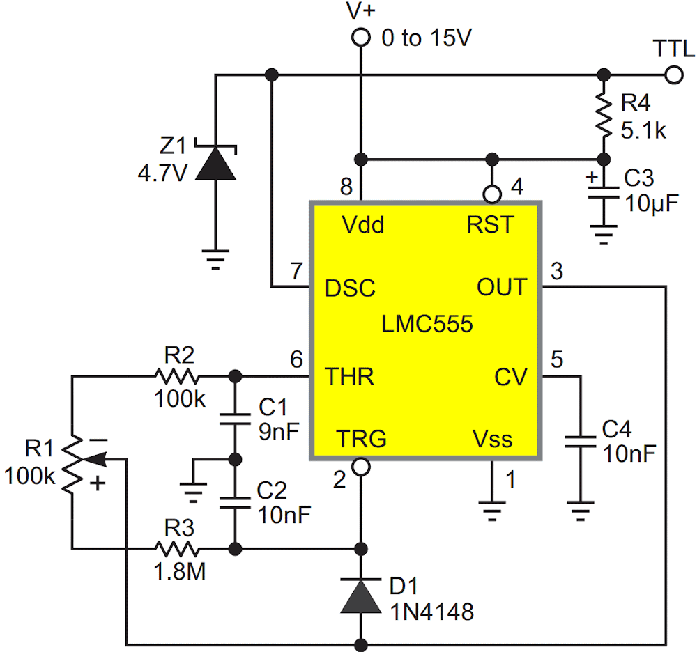
So I decided to work toward a Design Idea that would be more familiar (and friendly?), not needful of (too many) extra external components, (mainly) more accurate, and hopefully a bit cheaper. Figure 1 shows what my labors achieved.
 |
|
| Figure 1 | This Design Idea leverages a LMC555 as a variable duty cycle (1 ms to 2 ms = 5% to 10%), constant frequency (20 ms = 50 Hz) PWM oscillator. Timing is ratiometric and therefore independent of V+ so no external voltage regulator is needed. |
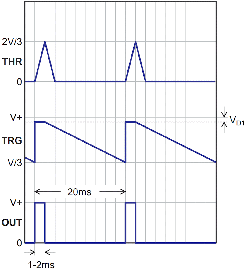
How it works is (roughly) sketched in Figure 2’s timing diagrams.
 |
|
| Figure 2 | The PWM oscillation cycle alternates between the Threshold pin for the duration of the 1 ms to 2 ms ON halfcycle is adjusted by R1, and the Trigger pin for the 18 ms to 19 ms OFF halfcycle. C2 > C1 to compensate for D1 forward drop. |
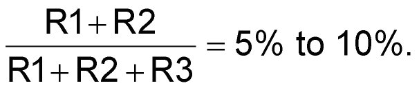
PWM duty cycle =
Oscillation frequency =
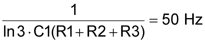
independently of R1 setting.
D1 recharges C2 during the PWM on interval. Z1 limits the output amplitude to TTL-safe levels. And given that LMC555s can be had for about a dollar in singles, I’d say the hoped-for price point box was also checked.
References
- Potash, Michael. "Simple, compact circuit conveniently controls devices and systems."