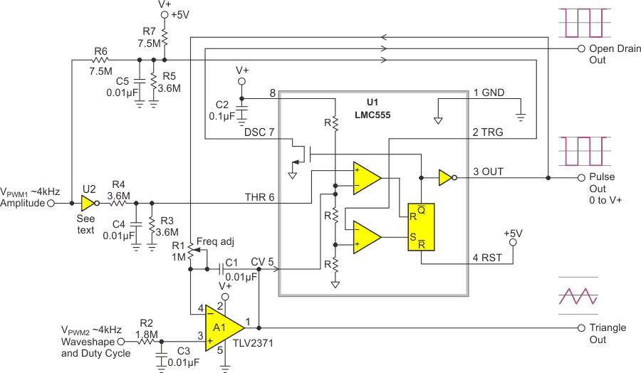
Circuit designs abound for linear triangle/sawtooth generators, and many are based on the iconic LMC555 CMOS analog timer. But relatively few are voltage controlled, making them tricky to program with a DAC, and most have unbuffered outputs that require additional components if more than a few microamps of load must be accommodated.
The oscillator in Figure 1 by contrast, has voltage DAC (e.g., PWM) controlled amplitude and waveshape, and actively buffered outputs. Here’s how it works:
 |
|
| Figure 1. | DAC controlled triangle/sawtooth generator with weird feedback. |
555-based oscillators (almost) universally rely on routing feedback from the output (OUT pin or DSC pin) through an RC integrator (passive or active) to input pins THR and TRG. But Figure 1 marches to a different drummer, controlling oscillation by routing feedback to the CV (control voltage) input instead. This is a peculiar ploy but has two worthwhile advantages.
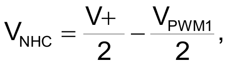
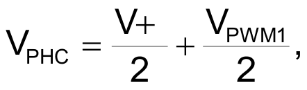
Using the CV pin for feedback frees up the THR and TRG pins to be used for the input of amplitude-control voltages that set the inflection points for A1’s integration ramp cycle. The negative-going half-cycle reverses direction when VCV descends to equal VTHR (VNHC), while the positive-going half-cycle flips when VCV rises to 2VTRG (VPHC). This makes it easy to program peak-to-peak oscillation amplitude (VPP) with a DAC-controlled input (VPMW1), inverter (U2), and R4 – R7 resistor network:

The result is illustrated in Figure 2.
 |
|
| Figure 2. | The triangle output amplitude versus VPMW1. |
Note that maximum VPP may ultimately be limited by the common mode limit of the 555’s THR comparator. This parameter isn’t specified in LMC555 data sheets, but for some examples of the device may be as high as 1 V. For such parts this would reduce max VPMW1, and therefore VPP, to 3 V. But that’s still nearly twice the usual 555’s oscillation amplitude of V+/3 = 1.67 V and so still pretty good. Oscillation frequency is inversely proportional to programmed VPP. U2 will typically be an element of a 74HC04 or similar chip.
Another nice feature of using CV this way is that feedback loop polarity is reversed. This neatly corrects for the signal inversion introduced by integrator A1, removing any need for a separate inverter. Also handy is that the TRG and THR inputs draw only picoamps of bias current. This allows use of multi-M resistances and small capacitances in the PWM ripple filtering networks without loss of accuracy and a reduction in power consumption that helps make total oscillator power consumption typically less than 4 mW.
A useful capability for a triangle generator is programmable production of both symmetric and asymmetric (sawtooth) waveforms. In this design, waveshape is controlled by VPMW2 as illustrated in Figure 3. Setting VPMW2 to 2.5 V yields a symmetrical triangle waveshape, while settings nearer 0 or 5 V produce sawteeth. A1’s rail-to-rail input will accept VPMW2 settings as close to ground or V+ as needed to generate the desired waveshape.
 |
|
| Figure 3. | The waveshape versus VPMW2. |
The duty cycle of Pulse Out also follows VPMW2, ranging from near 0% for VPMW2 near 0 V, to 50% for 2.5 V, and approaching 100% for VPMW2 near 5 V.
The uncommitted drain output DSC (plus a pullup resistor) is handy for output pulse amplitudes that differ from V+ or if the load to be driven is so heavy that connecting it to Pulse Out would erode oscillator accuracy.
The values shown for R1 and C1 are appropriate for operation in the range of 100 Hz to 1 kHz but can of course be changed to accommodate whatever frequency range is desired, up to a practical limit around 10 to 20 kHz.
V+ can go as low as 3 V to accommodate different logic supply voltages. Circuit operation will be unchanged except, of course, for maximum output amplitudes.