This circuit exemplifies the thesis that the 555 is to analog timing what the opamp is to analog “everything else”!
In any contest to see which is easier to manually program, digital potentiometers (dpots) suffer a big handicap when compared to traditional electromechanical pots.
No knob.
But henceforth, maybe that handicap won’t matter so much. This Design Idea implements a variable frequency oscillator circuit that produces dpot up/down steps. It generates step rates from zero to 20 Hz together with a separate up/down step direction signal. Both are controlled by simply (and quickly) twisting one knob on an inexpensive linear potentiometer (e.g. Bourns PTD90 series) a fraction of a turn.
Voila! There’s that long lost and longed for dpot knob at last! See the Figures that follow for how it works.
 |
|
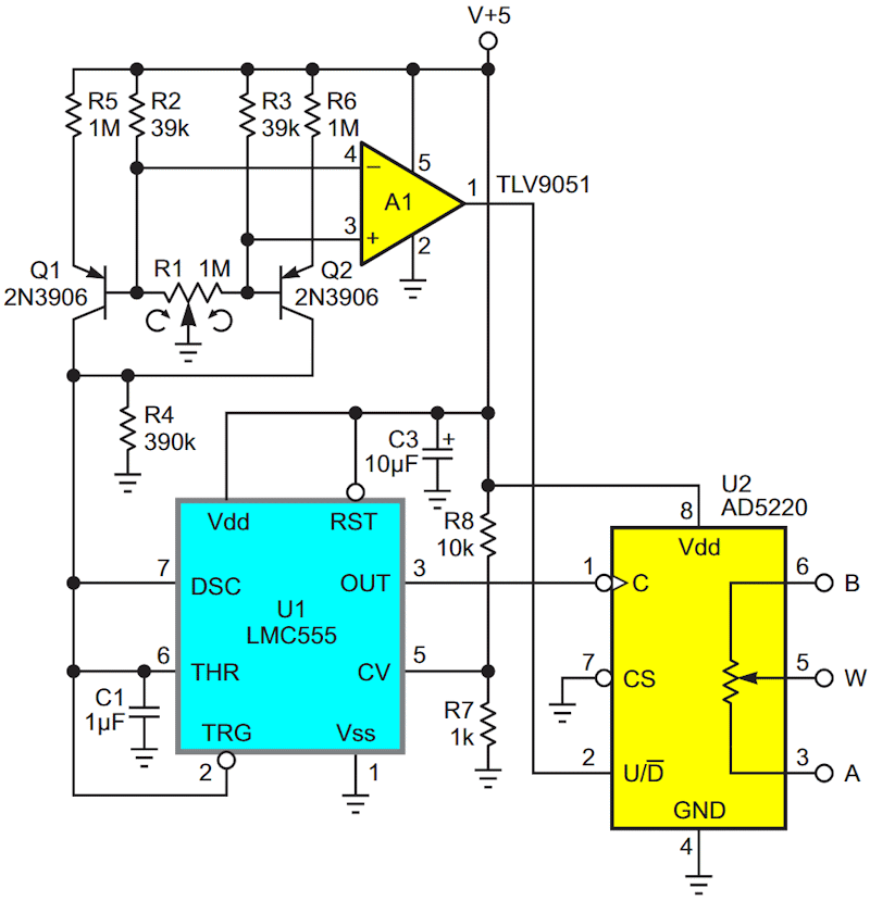
| Figure 1. | Current-to-frequency converter U1 generates dpot clock pulses at 20 Hz-0-20 Hz, controlled by the sum of Q1+Q2 collector currents set 0 to 5 µA by R1. A1 sets the up/down step direction. |
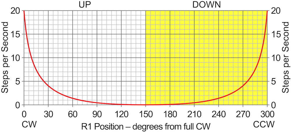
0 µA = 0 Hz corresponds to R1’s wiper centered at (or near) the midpoint of travel, and 20 Hz to both its clockwise and counterclockwise limits (Figure 1). Comparator A1 sets the dpot step direction to UP if R1’s wiper is clockwise of midpoint, DOWN for counterclockwise (Figure 2).
 |
|
| Figure 2. | This graph shows the dpot step rate and direction as a function of R1. |
Q1 sources the majority of current to U1 for UP steps, and Q2 takes over for DOWN. The VPP amplitude of the sawtooth waveform on C1 is set by the R7/R8 and 555 internal dividers to ~250 mV.
R1’s rest position is (anywhere near) midpoint where step rate = 0. Programming a new setpoint is done by the following steps.
- Turning R1 in the desired direction until stepping begins at a rate appropriate to the size of the intended setpoint change.
- Then gradually slowing the step rate to dead stop by returning R1 to midpoint as the new setpoint is approached.
Done.
With a “bit” of practice, a U2 setpoint change of 127 steps (maximum for the 7-bit resolution AD5220) can be accurately completed in less than 10 seconds. And if you feel the need for speed beyond that, there’s nothing easier.
Just back off on C1. Max step rate = 20 Hz/C1 for C1 in µF.
Related Content
- Woodward, Stephen. "DPOT push up/down."
- Woodward, Stephen. "Finger-friendly DPOT pushbuttons do ups, downs, and dittos."
- Woodward, Stephen. "Digital potentiometer simulates log taper to accurately set gain."
- Ramalingam, Jayapal. "Push to increase, decrease a digital potentiometer."
- Woodward, Stephen. "Synthesize precision bipolar Dpot rheostats."