In process-control applications requiring discontinuous controllers, the most elementary choice is a two-position-mode or on/off controller. A typical example of such a controller is a space heater. If the temperature drops below a setpoint, the heater turns on, and, if the temperature rises above the setpoint, it turns off. In the analog domain, the basis for the basic implementation of a two-position controller is an analog comparator or an open-loop operational amplifier. However, to avoid false switching, the typical implementation uses the well-known Schmitt trigger.
 |
|
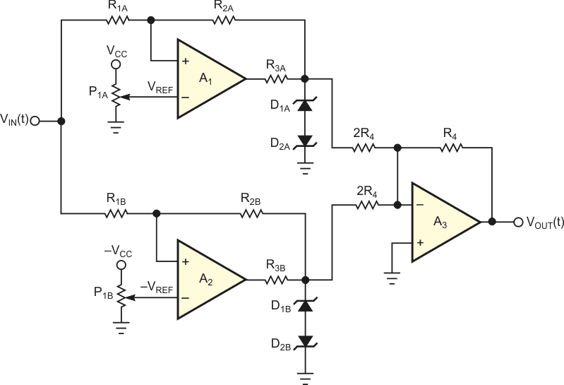
| Figure 1. | One straightforward way of obtaining a double-hysteresis-transfer characteristic uses three op amps with voltage references and zener diodes. |
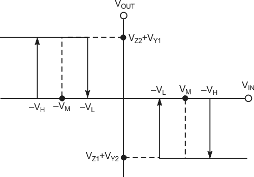
A logical extension of the two-position control mode is to provide several – rather than two – intermediate settings of the controller’s output. You can use this discontinuous-control mode to reduce the cycling behavior, overshoot, or undershoot inherent in the two-position mode. In fact, however, it is usually speedier to use some other mode when the two-position mode is unsatisfactory. The most common example is the three-position controller. Figure 1 shows one simple way to implement this controller. In this configuration, the Schmitt triggers around the operational amplifiers, A1 and A2, which implement the negative and positive hysteresis, respectively. You can replace A1 and A2 with analog comparators, such as an LM311 or similar. Figure 2 shows the I/O-transfer characteristic of the circuit in Figure 1:


and

VZ and VY are, respectively, the breakdown and the forward voltages of the four zener diodes.
 |
|
| Figure 2. | The I/O-transfer characteristic of the circuit in Figure1 exhibits two hysteresis bands. |
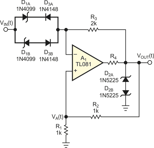
Figure 3 shows a more efficient way to implement a three-position controller. The circuit’s basis is a single operational amplifier, and it needs no reference voltages. The input and output diodes determine the upper high-voltage and lower low-voltage switching-threshold levels and the hysteresis of the comparator. Putting VIN(t) in the middle band eliminates the input diodes from the circuit, and the circuit is essentially a voltage follower with positive feedback. The output voltage follows VA(t), but the positive feedback establishing VA(t) sets this voltage at some fraction of the output voltage. So, two constraints define the output level in this circuit state: VOUT(t) = VA(t), and

 |
|
| Figure 3. | This circuit achieves dual hysteresis using only one op amp. |
The only condition satisfying these two constraints is that VOUT and VA = 0 V; so, the output remains at 0 V when the input diodes are reverse-biased. A 0 V output state continues until input voltage increases with positive or negative values. Then, one of the two input zener diodes conducts, driving the amplifier output positive or negative at an input voltage of ±VH. In this condition, when absolute input voltage decreases, the amplifier output again goes to 0 V at an input voltage of ±VL. Thus, the design equations for VH and VL are

and

 |
|
| Figure 4. | This oscilloscope trace shows the transfer characteristic of the circuit in Figure 3. |
Figure 4 shows the I/O-transfer characteristic of the circuit with the values in Figure 3, where D1A and D1B are 6.8 V 1N4099 zener diodes and D2A and D2B are 3 V 1N5225 zener diodes. Figure 5 shows the output voltage when you apply a triangular waveform at the circuit’s input.
 |
|
| Figure 5. | This oscilloscope trace shows the response of the circuit in Figure 3 to a triangular input waveform. |