Many recent Design Ideas (Ref, 1) have involved button-pushing to control power. Some may have been more resistant to contact-bounce than others – but how can we really check that? This DI describes how some simple circuitry can simulate bouncy contacts, and do so controllably and repeatably, thus allowing an objective measure of how well the debouncing works.
Other solutions are available! Capturing the bounces from a real switch and then replaying them at varying rates is one approach, and SPICE models are apparently available. I’ve not played with the latter, but trust that its developers had fun simulating some truly evil conditions.
Genuine contact noise is inherently random and often very spiky. This device, shown in detail in Figure 1, uses bursts of well-defined pulses instead. If your debouncing circuitry or code can handle those, real-world operation is pretty much guaranteed. Because these pulses are grouped in bursts and are repeatable, the guard time can easily be measured. Hook this across the (normally-open) contacts whose debouncing you need to check, and vary the burst duration until your system misbehaves.
Push switches vary a lot, as some quick tests revealed. Clicky tact(ile) ones showed little or even no bounce when closing. A cheap doorbell push was, putting it politely, somewhat worse, though admittedly it was intended to switch a contact-cleaning amp or so. While most were noisier when opening than closing, they were generally stable within 20 ms (doorbell button excepted), so the span of 100 µs to 100 ms should be adequate for testing.
 |
|
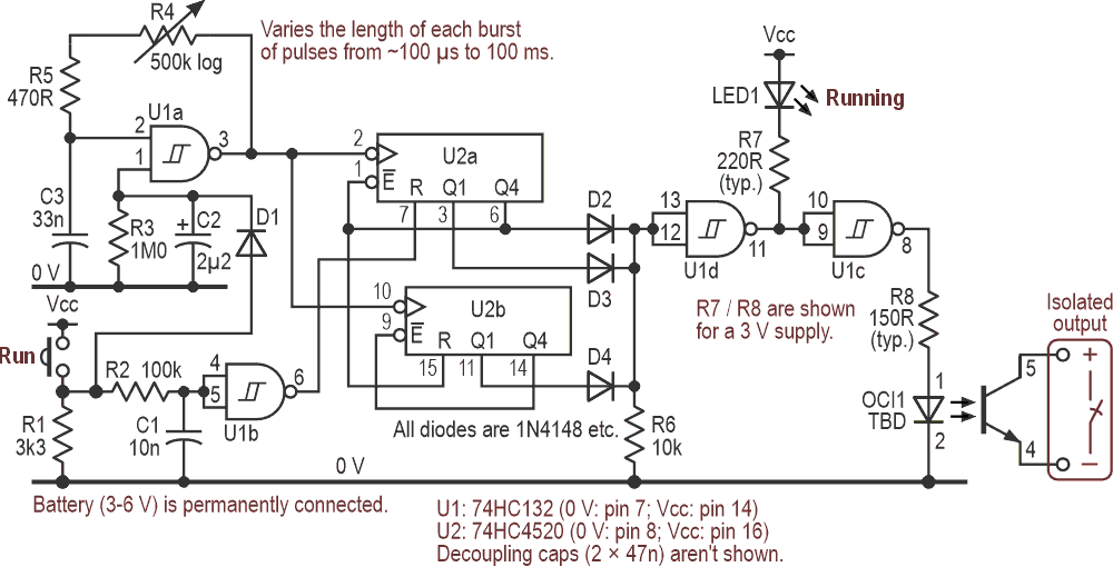
| Figure 1. | This contact-bounce simulator generates brief bursts of pulses when the Run button is either pressed or released, the burst durations ranging from about 100 µs to 100 ms. The optocoupler provides an isolated output that can pull up or down as needed. |
Until the Run button is pressed, oscillator U1a is inhibited and the circuit is static, so no power is drawn – nanoamp leakages excepted – and the output is open circuit. Pressing Run enables the oscillator. After a brief delay (C1/R2) to mask the initial clock edge, it also clears U2a’s reset, allowing U2a to count up to 8 and then freeze or dead-end itself. Pulses from its Q1 are indirectly fed to the optocoupler OCI1 to simulate the “making” bounces, followed by a steady level from Q4 once the switch is deemed to be properly closed. U2b is inactive during this sequence. Figure 2 shows the various waveforms.
 |
|
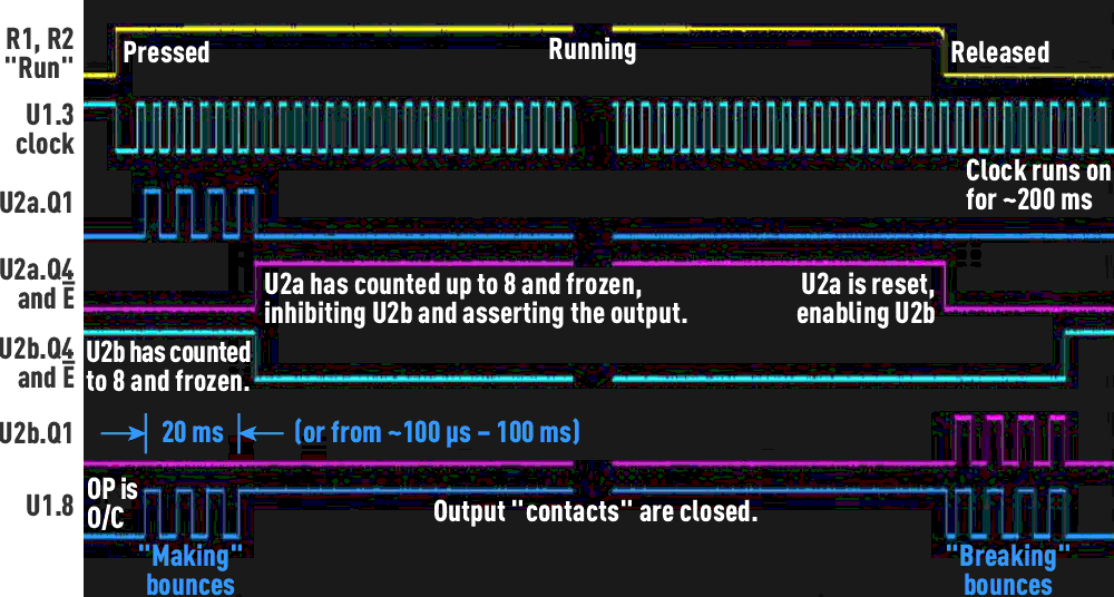
| Figure 2. | A composite of waveforms from the circuit of Figure 1, with some notes on its operation. |
What’s pushed down must come up
When Run is released, C2 and R3 ensure that the oscillator still operates for ~200 ms. U2a is reset, clearing the steady “on” condition and allowing U2b to count up while its Q1 delivers the “breaking” bounces. Finally, U2b freezes, and everything can turn off, ready for the next test cycle.
D2–4 and R6 OR the pulses and the steady level. The first attempt used a 74HC02 (quad NOR) to do that, but there were so many odd gates left over that it all just looked unhappy. Employing diode logic plus the spare U1 gates for buffering cured that.
This view of the waveforms exposes a slight hiccup! Note how the making and breaking sequences differ, with the latter starting at an arbitrary point on the clock, giving an extra pulse or part thereof. Adding more logic could have cured that by synchronizing U2a’s reset with the clock, but while more elegant ’scope-wise, it had no practical advantage. Anyway, as we saw above, many buttons are electrically noisier when their contacts are opening.
An easy way out, and a harder one
Now that we have the bursts, we need to make them look like actual switch closures. The simplest and generally best way is to drive them into the LED of an optocoupler, as shown in Figure 1. Its transistor is the output switch, which can pull up or down as required. Its effective resistance may be significant; an (obsolete) FCD820 driven with ~7 mA looked like ~500 Ω.
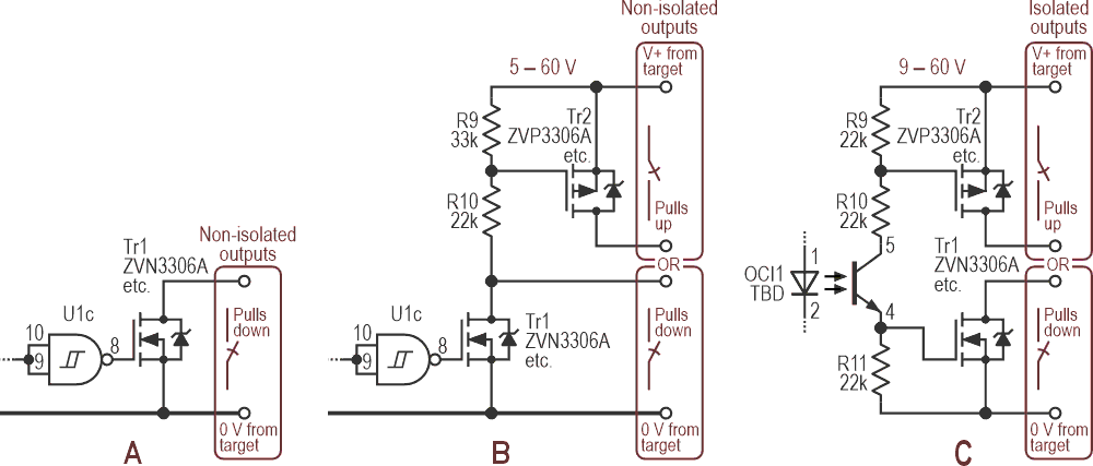
That’s fine for logic-level applications, but if more grunt is needed, MOSFETs are better because they conduct much harder. Figure 3 shows some add-on variants ranging from simple pull-down and pull-up/pull-down circuits – both non-isolated – to a fully isolated arrangement. Note the necessary power and ground feeds from the target. The devices shown are good for 60 V, a few ohms, and moderate currents.
 |
|
| Figure 3. | MOSFETs can be used to switch the output with much less “contact resistance.” This shows three ways of doing that, with both isolated and non-isolated outputs. |
Isolating the output with a reed relay is a non-starter. They take several milliseconds to respond, which is slower than we need, and chatter badly (mercury-wetted ones excepted). On a positive note, this gadget can easily simulate them, at least for simple makes or breaks: replace the Run button with a suitably-driven OCI.
A digression and a rant
Why do many single-function buttons refuse to do anything useful until they are released? With multi-function ones – perhaps intended to distinguish between short presses, long ones, and being inadvertently sat on – it makes good sense, but when there are no other options, it’s irrational. Once a switch has been seen as valid for long enough, it should be treated as such. I can’t be alone in having an almost instinctive reaction to delayed results: either “Ooh – there must be other options” or “Arggh – it’s broken”, neither of which is usually true or helpful.
Though I did accidentally find the (undocumented) subtitles’ control on the remote for my new TV by holding the mute button down for too long. According to said documentation, that function was inaccessibly buried – in the Accessibility Menu. Buttons often seem to be seen as trivial afterthoughts, but when they are part of a user interface, they need to be implemented (and debounced) with subtlety and care. And properly documented for the user. End of rant.
Reference
- Cornford, Nick. "To press on or hold off? This does both."