Using the concept and leveraging the example circuits in this Design Idea, you can divide any frequency by any number divisible by 2.
Any dividend frequency can be divided by any number representable by 2n, resulting in a square wave output quotient with a 50% duty cycle, using binary counters. Unfortunately, this capability is not more broadly applicable to other divisor numbers, at least directly. I had a requirement to do frequency division of a square wave signal by 10, resulting in a 50% duty cycle output, for use in a PLL (phase lock loop) based project. This objective is not directly achievable by any IC I’m aware of.
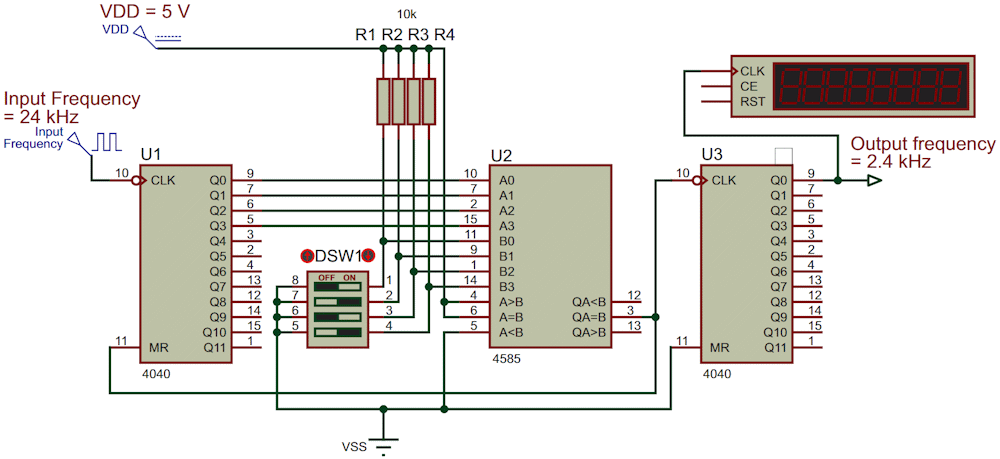
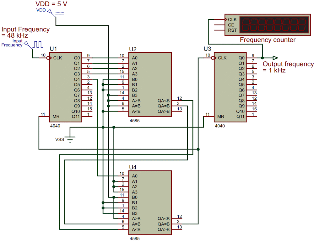
Hence, I came up with the circuit shown in Figure 1. Here, the input frequency is first divided by 5 and then by 2, resulting in a 50% duty cycle waveform. Using this idea, you can divide any frequency by any number which itself is divisible by 2. For example, extending the concept, the circuit in Figure 2 divides by 48, again with a 50% duty cycle output. The first stage divides by 24, and the second stage divides by 2.
 |
|
| Figure 1. | This circuit divides the input frequency by 10. The output is a 2.4 kHz square wave with a 50% duty cycle. The ICs’ power supply and ground pins are not shown. For division by other numbers, change the DIP switch (DSW1) setting: OFF=1, ON=0. |
How does Figure 1’s circuit work? U1 is a 12-stage counter. The input square wave is connected to U1’s CLK input. U2 is a 4-bit digital comparator. It has 4 inputs (A0 to A3), along with another 4 inputs (B0 to B3) for comparison purposes. It also has 3 more cascading inputs (A>B, A=B, A>B). U2 is wired for divide-by-5 by setting the DIP switch to value 0101. And its cascading inputs are wired per the 4585 datasheet (PDF).
U2’s QA=B output goes HIGH after every 5th count of U1. It increments U3 and simultaneously resets U1, which restarts counting from zero. The U2 QA=B output is divided by 2 by U3; U3’s Q0 output ends up being the input frequency divided by 10, with a 50% duty cycle. Since U2 is a 4-bit comparator, this circuit can be used for frequency division by any number (N) up to 24, prior to final division by 2. Set the DIP switch accordingly for N (OFF=1, ON=0). The total division is by 2N. Hence, Figure 1 is a circuit that divides an input frequency by N, where N is conveniently settable by a DIP switch.
How does Figure 2’s circuit work? As previously noted, it’s just an extension of the one in Figure 1, in this case dividing the input frequency by 48. It first divides by 24 and then by 2. The binary representation of 24 is 00011000. To accommodate the design objective, a second 4585 comparator U4 is added, cascading with U2. U2’s A0 to A3 inputs, along with A0 of U4, are connected to U1’s Q0 to Q4 outputs. And U4’s B0, along with U2’s B0 to B3, are hardwired as 11000 (24).
 |
|
| Figure 2. | This circuit divides the input frequency by 48. The output is a 1 kHz square wave with a 50% duty cycle. It uses two 4585 comparators (U2 and U4) connected in cascade. Again, the ICs’ power supply and ground pins are not shown. The same circuit can also be used for division by other numbers (see the text for more information). |
No DIP switch is included this time, although one may be added if necessary for further design flexibility. The cascading outputs and inputs are again connected as per the 4585 IC datasheet. U4’s Q4=B output is connected to the clock input of U3 and to MR of U1. Hence, counter U1 counts up to 24 and then resets to start from zero. U3’s CLK input is therefore one per 24 pulses, and is further divided by 2. The resultant U3 Q0 output is the input frequency divided by 48, with a 50% duty cycle.
The circuit in Figure 2 can be used to initially divide by any number up to 28, and then by 2 in the next stage. To accomplish this objective, connect Q4, Q5, Q6 and Q7 of U1 to A0, A1, A2 and A3 of U4. Set the divisor in binary by appropriately connecting B0, B1, B2 and B3 of U2 and B0, B1, B2 and B3 of U4 to either “1” or “0” (VDD or VSS). And the idea can be further extended for division by any number by suitably selecting counters and the number of cascaded 4585 comparators.
Related content
- Wyatt, Mike. "Injection locking acts as a frequency divider and improves oscillator performance."
- Michael A. Shustov. "Frequency divider from 1 to 4096 in increments of 1."