This project made me feel a kind of kinship with Diogenes, although I was searching for the item described in the title rather than for an honest man.
 |
|
| Figure 1. | “Diogenes Looking for an Honest Man,” a painting attributed to Johann Heinrich Wilhelm Tischbein (1751-1829). The author of this DI has a more modest goal. |
I wanted a design that did not require the evaluation and selection of one out of a group of components. I’d tolerate (though not welcome) the use of frequency compensation and even an automatic gain control (AGC) to achieve predictable performance characteristics. Let’s call my desired design “reliably repeatable.”
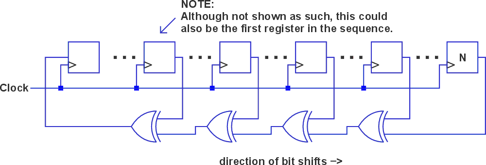
Standard MLS digital circuit
Initially, I thought none of the listed accommodations would be necessary, and that a simple well-known digital circuit – a maximal length sequence (MLS) Generator [1] – would fit the bill. This circuit produces a pseudorandom sequence whose spectral characteristics are white. A general example of such is shown in Figure 2.
 |
|
| Figure 2. | The general form of an MLS generator. A reference lists a table of 2 to 5 specific taps for register lengths from N = 2 to 32 to produce repeating sequences of length 2N-1. Register initialization must include at least one non-zero value. The author first listened to a version using only one exclusive or gate with N = 31 registers, in which the outputs of only the 28th and 31st registers were sampled. |
It was simple to code up the one described in the Figure 2 caption with an ATtiny13A microprocessor and obtain a 1.35 µs clock period. Of course, validation is in the listening. And indeed, the predominant sound is the “shush” of white noise.
But there are also audible pops, clicks, and other unwanted artifacts in the background. I had a friend with hearing better than mine listen to confirm my audition’s disappointing conclusion. And so, I picked up my lantern and moved on to the next candidate.
Reverse-biased NPN
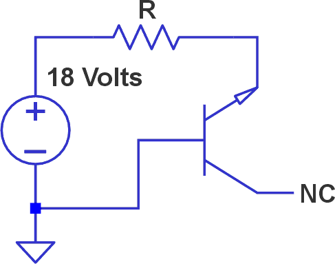
I was intrigued by reverse-biasing a transistor’s base-emitter junction with the collector floating (see Figure 3).
 |
|
| Figure 3. | Jig for testing the noise characteristics of NPN transistors with reverse-biased base-emitter junctions. |
I tested ten 2N3906 transistors with values of R equal to 103, 104, 105, and 106 ohms. Both DC voltages and frequency sweeps (of voltage per square-root spectral densities in units of dBVrms /√Hz) were collected.
It was evident that as R decreased, average noise decreased and DC voltages rose slightly, remaining in the range between 7.2 and 8.3 volts. This gave me hope that a simple AGC scheme in which the transistor bias current was varied might satisfy my requirements.
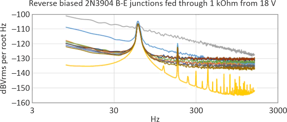
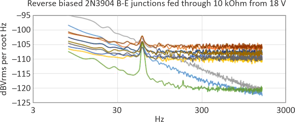
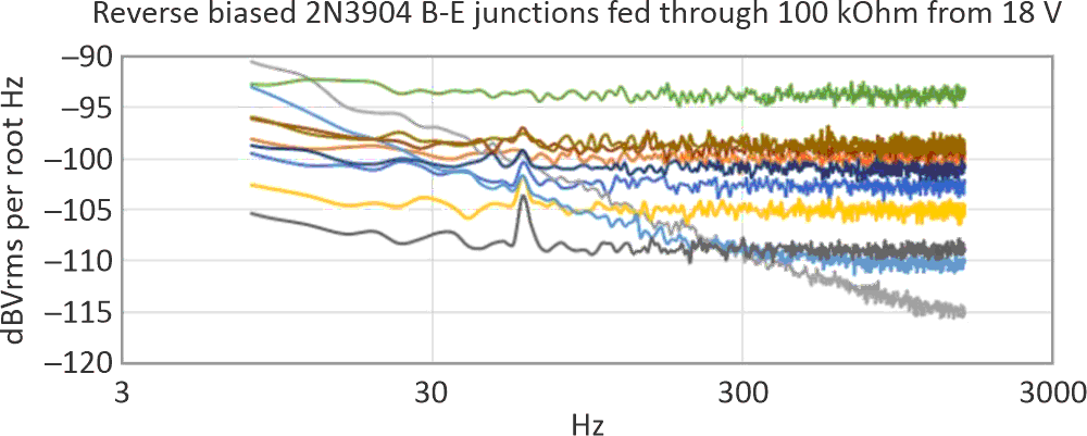
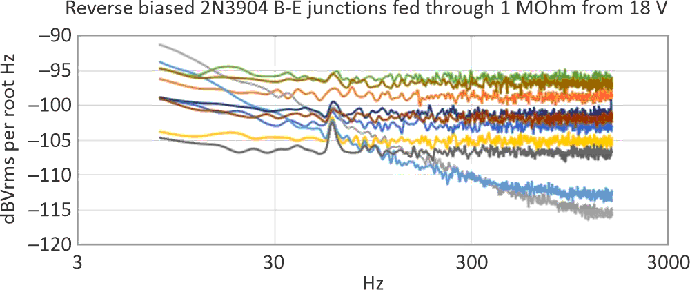
Alas, it was not to be. Figure 4a, Figure 4b, Figure 4c, and Figure 4d show spectral noise in the lower frequency range. (Additional filtering of the 18-V supply had no effect on the 60 Hz power line fundamental or harmonics – these were being picked up from my test environment. The 60-Hz fundamental’s level was about 10 µV rms.)
 |
|
| Figure 4a. | Note the power line harmonics “hum” problem that the “quiet orange” transistor in particular introduces. |
 |
|
| Figure 4b. | Biasing the “orange” transistor at a lower current raised the noise and hid the power line harmonics, but not the fundamental. |
 |
|
| Figure 4c. | As the bias current is reduced, some but not all transistors’ noises mask the 60 Hz fundamental. |
 |
|
| Figure 4d. | Regardless of whether the power line noise can be masked or eliminated, it’s clear for all resistor R values that there is no consistent shape to the frequency response. |
I’ve tried other transistors with similar results. Being unable to depend on a specific frequency response shape, the reverse-biased base-emitter transistor is not a suitable signal source for a reliably predictable design. It’s time to pick up the lantern again and continue the search.
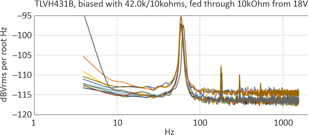
A shunt regulator
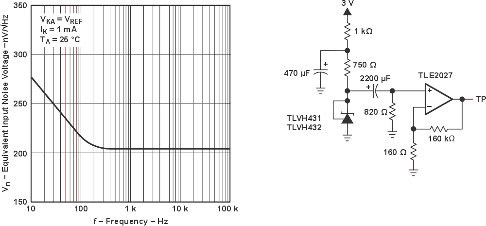
Within several datasheets of components in the ‘431 family and in the TLVH431B’s in particular, there is a figure showing the devices’ equivalent input noise. See Figure 5.
 |
|
| Figure 5. | The equivalent input noise and test circuit for the TLVH431B (Figure 5-9 in the part’s datasheet). |
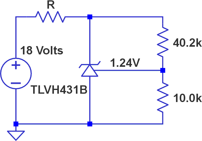
The almost 3 dB of rise in noise from 300 Hz down to 10 Hz could be compensated for if it were repeatable from device to device. I looked at the cathode of ten devices using the test jig of Figure 6. The spectral responses are presented in Figure 7.
 |
|
| Figure 6. | The test jig for TLVH431B spectral noise. There was no significant difference in the results shown in Figure 7 when values of 1 kΩ and 10 kΩ were used for R. 100 kΩ and 1 MΩ resistances supplied insufficient currents for the devices’ operation. |
 |
|
| Figure 7. | The TVH431B spectral noise, 10 samples with the same date code. |
Although the TLVH431B is a better choice than the 2N3904, there are still variations in its noise levels, necessitating some sort of AGC. And the power line signals were still present, with no mitigation available from different values of R. The tested parts all have the same date code, and there are no numerical specs available for limits on noise amplitudes or frequency responses.
Who knows how other date codes would behave? I certainly can’t claim from the data that this component could be part of a “reliably repeatable” design as I defined the term. But you know what? Carrying this lantern around is getting to be pretty annoying.
Xorshift32
I kept thinking that there had to be a digital solution to this problem, even if it couldn’t be the one that produces an MLS. I did some research, and the option of what is called “xorshift” came up, specifically xorshift32 [2].
Xorshift32 starts by initializing a 32-bit variable to a non-zero value. A copy of this variable is created, and 13 zeros are left-shifted into the copy, eliminating the 13 left-most original register values.
The original and the shifted copy are bit-for-bit exclusive-OR’d and stored in the original variable. A copy of this result is made. 17 zeros are then right-shifted into the copy, eliminating the 17 right-most copy’s values. The shifted copy is again exclusive-OR’d bit-by-bit with the updated original register and stored in that register.
Again, a copy of the original’s latest update is made. 5 zeroes are left-shifted into the newest copy, which is then exclusive-OR’d with the latest original update and stored in that original. As this three-step process is repeated, a random sequence of length 232-1 consisting of unique 32-bit integers is generated.
This algorithm was coded into an ATtiny13A microprocessor running at a clock speed of 9.6 MHz, yielding a bit shift period of 5.8 µs. (Assembly source code and hex file are available upon request.) The least significant register bit was routed to bit 0 of the device’s PORTB (pin 5 of the eight-pin PDIP package.)
This pin was AC-coupled to a power amplifier driving a Polk Audio bookshelf speaker. My friend and I agreed that all we heard was white noise; the pops and clicks of the MLS sequence were absent.
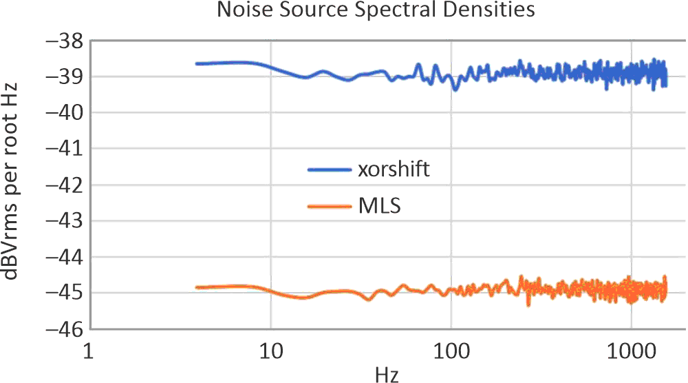
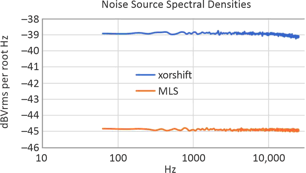
Figure 8 and Figure 9 display frequency sweeps of the voltage per square-root spectral densities of the MLS and the xorshift sequences.
 |
|
| Figure 8. | Noise spectral densities from 4 to 1550 Hz of the two auditioned digital sequences produced with 5 V-powered ATtiny13A microprocessors. |
 |
|
| Figure 9. | Noise spectral densities from 63 to 25000 Hz of the two auditioned digital sequences produced with 5 V-powered ATtiny13A microprocessors. |
There are a few takeaways from Figures 8 and 9.
The white noises of the sequences are at high enough levels to mask my testing environment’s power line fundamental and harmonics that are apparent when evaluating the 2N3904 and the TLVH431B.
The difference in levels of the two digital sequences is due to the higher clock rate of the MLS, which spreads the same total energy as the xorshift over a wider bandwidth and results in a lower energy density within any given band of frequencies in the audible range.
Finally, the xorshift32 has a dip of perhaps 0.1 dBVrms per root Hz at 25 kHz. If the ATtiny13A were clocked from an external 20-MHz source, even this small response dip would disappear.
Audibly pure white noise source
An audibly pure white noise source for the band from sub-sonic frequencies to 20 kHz can be had by implementing the xorshift32 algorithm on an inexpensive microprocessor.
The result is reliably repeatable, precluding the need to select an optimal component from a group. The voltage over the audio range is:
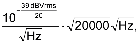
which evaluates to a 1.6-Vrms signal. This method has none of the disadvantages of the analog noise sources investigated. There is no need to deal with low values and uncertainties of signal level, necessitating the application of a large amount of gain and an AGC, frequency-shaping below 300 Hz or elsewhere, and environmental power line noise at levels comparable to the intentional noise.
I can finally put that darn lantern down. I wonder how Diogenes made out.