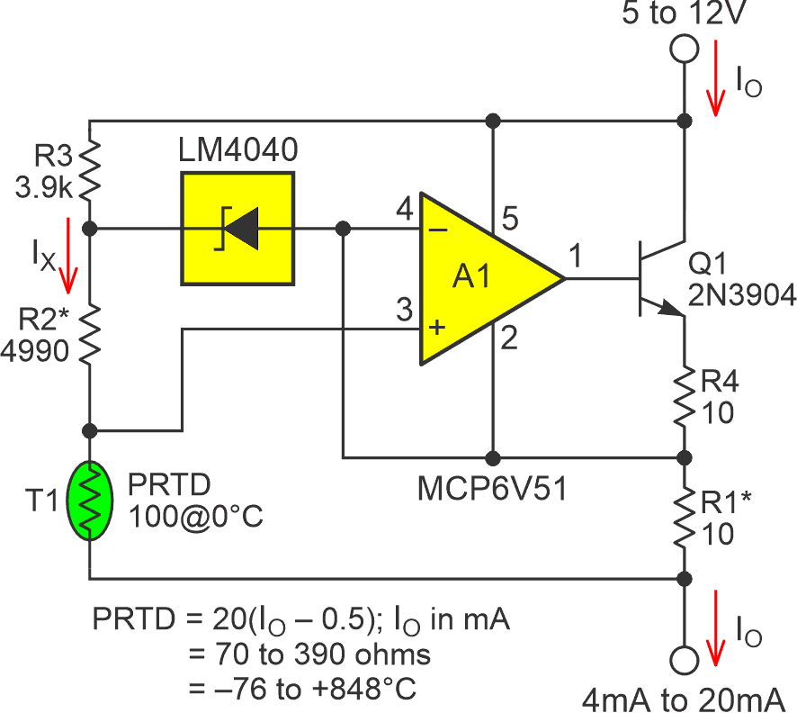
I recently published a simple design (Ref. 1) for a platinum resistance detector (PRTD) 4 to 20 mA transmitter circuit, illustrated in Figure 1.
 |
|
| Figure 1. | The PRTD 4 to 20 mA loop transmitter with constant current PRTD excitation that relies on 2nd order software nonlinearity correction math. |
The simplicity of Figure 1’s circuitry is somewhat compromised, however, by its need for PRTD nonlinearity correction in software:
where u and w constant and x = RPRTD@0°C – RPRTD@0°T.
Unfortunately, implementing such quadratic floating-point arithmetic in a small system might be inconveniently costly in code complexity, program memory requirements, and processing time.
But fortunately, there’s a cool, clever, comparably accurate, code-ware-lite, and still (reasonably) uncomplicated alternative (analog) solution. It’s explained in this article “Design Note 45: Signal Conditioning for Platinum Temperature Transducers” (Ref. 2) by (whom else?) famed designer Jim Williams.
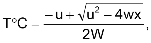
Figure 2, shamelessly copied from William’s article, showcases his analog solution to PRTD nonlinearity.
 |
|
| Figure 2. | A platinum RTD bridge where feedback to the bridge from A3 linearizes the circuit. |
Williams explains:
The nonlinearity could cause several degrees of error over the circuit’s 0 °C to 400 °C operating range. The bridge’s output is fed to instrumentation amplifier A3, which provides differential gain while simultaneously supplying nonlinearity correction. The correction is implemented by feeding a portion of A3’s output back to A1’s input via the 10k to 250k divider. This causes the current supplied to Rp to slightly shift with its operating point, compensating sensor nonlinearity to within ±0.05 °C.
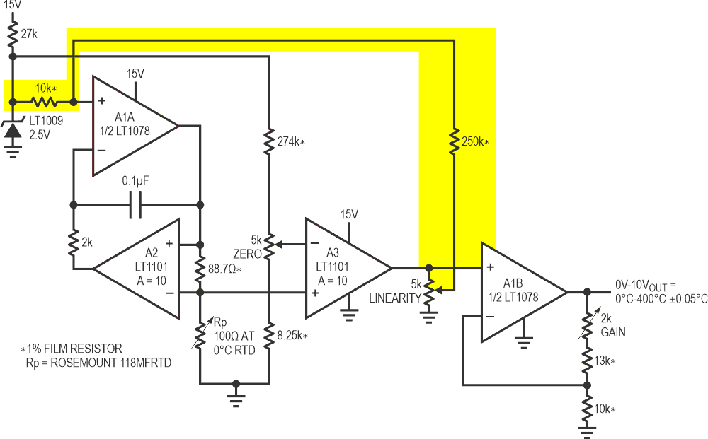
Figure 3 shows William’s basic idea melded onto Figure 1’s current transmitter concept.
 |
|
| Figure 3. | A PRTD transmitter based on the classic LM10 op-amp plus a 200 mV precision reference combo. |
R5 provides PRTD-linearizing positive feedback to sensor excitation over the temperature range of –130 °C to +380 °C.
Here, linearity correction is routed through R5 to the LM10 internal voltage reference, where it is inverted to become positive feedback. The resulting “slight shift in operating point” (about 4% over the full temperature range) duplicates William’s basic idea to achieve the measurement linearity plotted in Figure 4.
 |
|
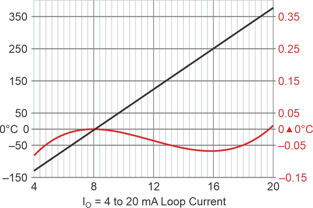
| Figure 4. | Positive feedback reduces linearity error to < ±0.05 °C over –127 °C to +380 °C. The x-axis = IO (mA), left y-axis = PRTD temperature, right y-axis = linearity error. T°C = 31.7(IO – 8 mA). |
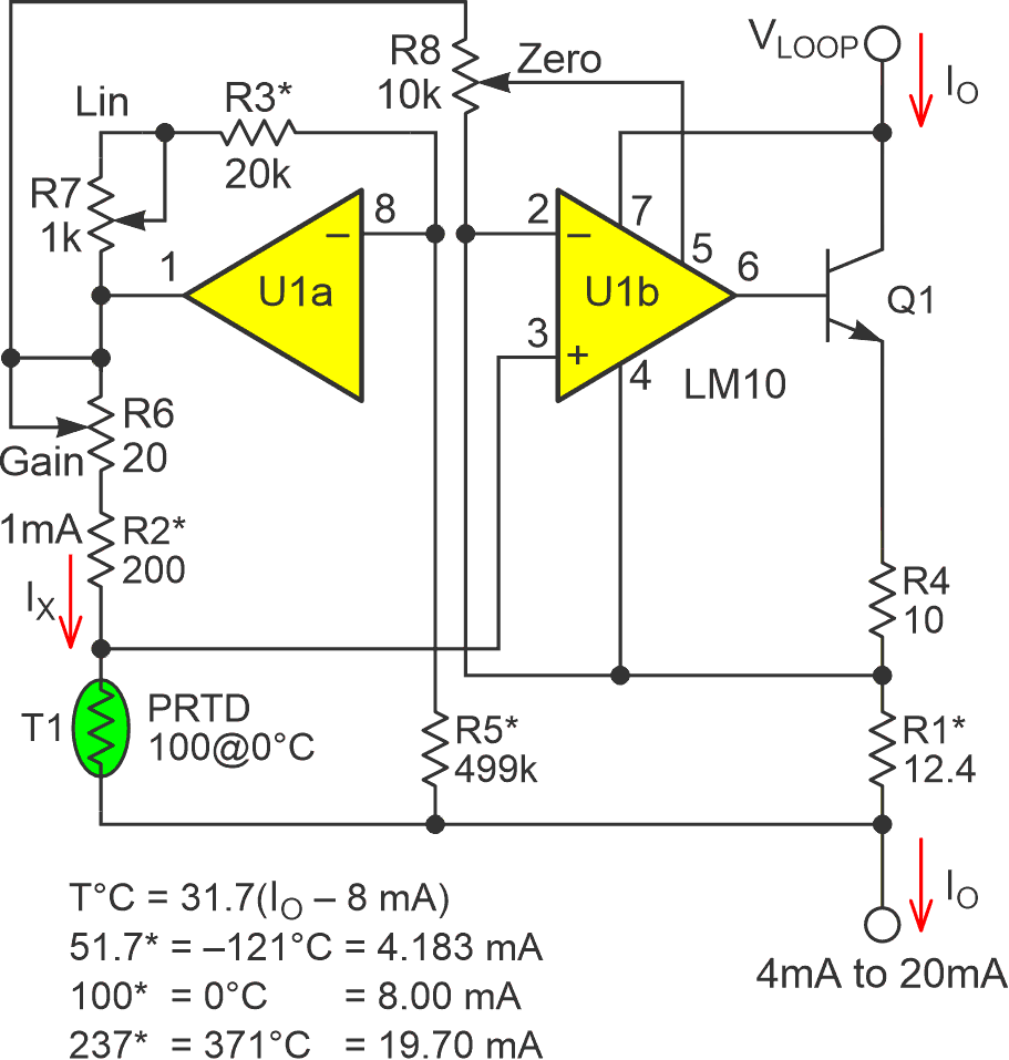
Of course, to consistently achieve this ppm level of accuracy and linearity probably needs an iterative calibration process like the one William’s describes. Figure 5 shows the modified circuit from Figure 3, which includes three additional trims to enable post-assembly tweaking using his procedure.
 |
|
| Figure 5. | Linearized temperature transmitter modified for a post-assembly tweaking using his procedure. |
Substituting selected precision resistors for the PRTD at chosen calibration points is vital to making the round-robin process feasible. Using actual variable temperatures would take impossibly long! Unfortunately, super precise decade boxes like the one William’s describes are also super scarce commodities. So, three suitable standard value resistors, along with the corresponding simulated temperatures and 4-20 mA loop currents, are suggested in Figure 5. They are:
51.7 Ω = –121 °C = 4.183 mA
100 Ω = 0 °C = 8.000 mA
237 Ω = 371 °C = 19.70 mA
Happy tweaking!
Oh yeah, to avoid overheating in Q1, it should ideally be in a TO-220 or similar package if VLOOP > 15 V.
References
- Woodward, Stephen. "Simple but accurate 4 to 20 mA two-wire transmitter for PRTDs."
- Williams, Jim. "Signal Conditioning for Platinum Temperature Transducers."