Minimal circuit converts input frequency to a precision current source that also accommodates grounded inputs.
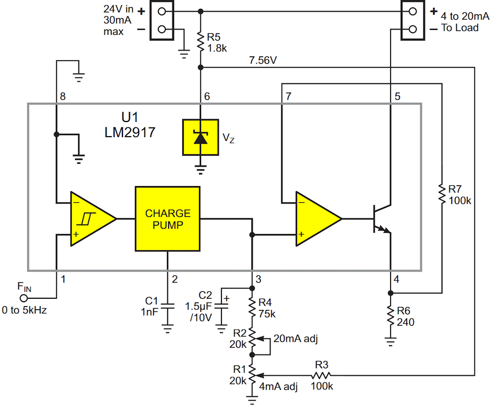
I recently had the opportunity to share a design (Ref. 1) for frequency to current loop conversion using the versatile (if somewhat ancient) LM29x7 series. Taking shameless advantage of the flexibility of these legacy devices, that minimalist design made do with just nine paltry passive parts. Figure 1 shows its (nearly painful) simplicity (so simple it almost Hz).
 |
|
| Figure 1. | In this circuit, the LM2917 needs no added actives to make a frequency to 4-20 mA current sink converter. |
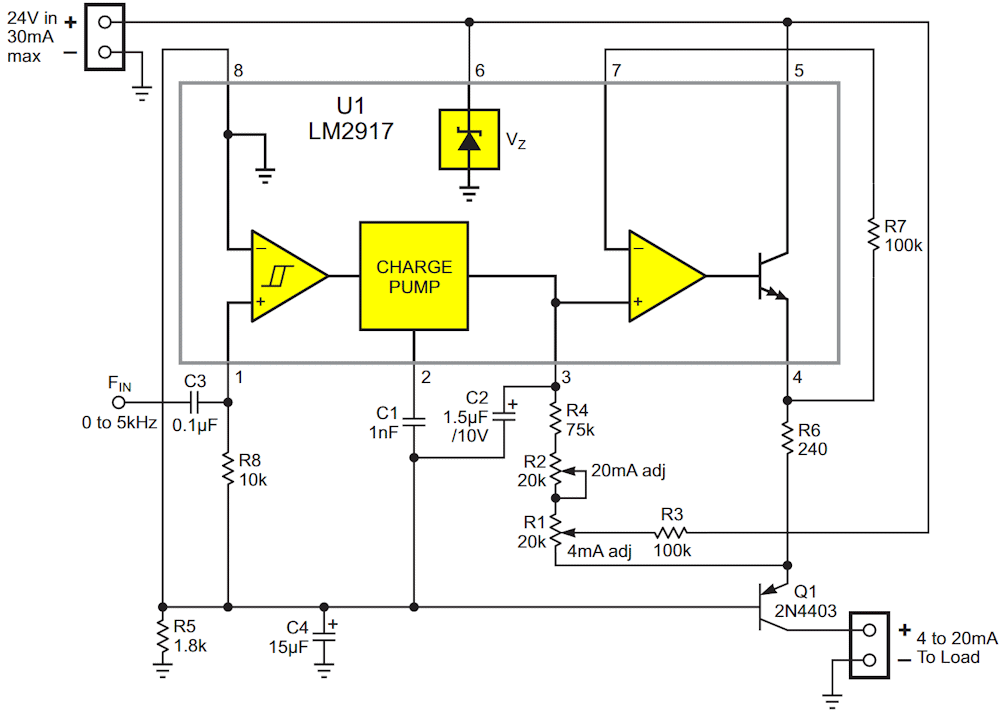
However, it was pointed out in the comments (thanks, RJ! [2]) that its current sink output may not be compatible with some industrial control and monitoring hardware. So here comes Figure 2 with a frequently friendlier current source output.
 |
|
| Figure 2. | Four frugal extra external parts (bringing the total to 13) convert Figure 1 into a flexible current source that’s useful if the load is grounded. |
Converting Figure 1’s converter from current sink to current source begins with tying pin 6 to the +24 V rail. This lets the internal voltage shunt reference Z1 float the internal “ground” reference pin 8 at 16.4 V instead of at zero. R5 provides the necessary bias current (just as it does in Figure 1), and C4 gives us some noise-bypassing insurance. Adding cascode (Ref. 3) Q1 completes the conversion.
Although U1’s spec’d linearity and temperature coefficient are good, its initial tolerances aren’t so great. Therefore some post-assembly final calibration is unavoidable, which necessitates R1’s (4 mA zero) and R2’s (20 mA full-scale 5 kHz) tweakability. If you do the adjustments in the right order (first R1, then R2), they won’t interact, and calibration can be completed in s single pass.
An additional helping of flexibility comes from the fact that, if your application doesn’t need or want a 4 mA baseline current, just omit R3. Then adjust R2 normally for a top end of 20 mA. That’ll give 0-20 mA with no other mods required.
References
- Woodward, Stephen. "Painlessly convert Hz to 4-20mA current loop."
- Jayapal Ramalingam
- Cascode